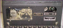
US Navy RTTY Equipment - Terminal Units
(Combined Keyer + Converter)

RTTY is also called RATT (Radio Teletype)


AN/URA-17E diversity system is composed of  two CV-3510A/UG
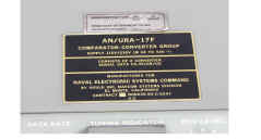
AN/URA-17F diversity system is composed of two CV-3510B/UG
AN/URA-17G diversity system is composed of two CV-3510C/UG

Note: AN/URA-17, -17A, -17B, -17C, -17D are receiving converter systems only, using CV-483/URA-17

AN/SGC-1, AN/SGC-1A
(TT-40/SGC-1, TT-40A/SGC-1)

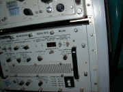
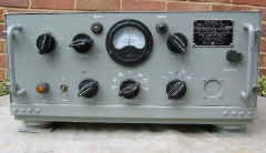
sgc-1-01.jpg (15563 bytes)
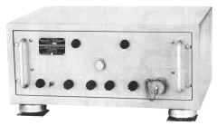
AN/SGC-1

sgc-1-mod-01.jpg (20319 bytes)
AN/SGC-1 modified for ham use

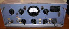
sgc1a-101.jpg (27458 bytes)
AN/SGC-1A (modified from -1?)

sgc1-12.jpg (73157 bytes)
Later AN/SGC-1A

Early AFSK Terminal Unit (demod and keyer) primarily used shipboard for UHF RTTY links. 

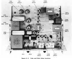
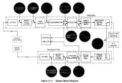
detailed circuit description and schematic

See connection info below

200 cps shift (700cps mark, 500 cps space). Can be readily converted to other shift freq. 

NAVSHIPS 91152 (SGC-1)

NAVSHIPS 91503 (SGC-1A) - available from WA5CAB

See CQ magazine April 1970, page 82, for info (avail at http://hamcall.net/cq)

manuf - Remler

CV-2460/SGC

cv2460sgc-01.jpg (18909 bytes)

AFSK Terminal Unit
(converter and keyer)

A = 500Hz space / 700Hz mark (UHF)
B = 1575Hz space / 2425Hz mark (HF)

Note: these are reverse polarity to CV-3510 below

- manuf - Stelma

manual NAVELEX EE162-AB-MMO-010/E110

Operating info (630kb pdf) 

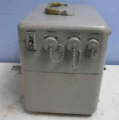
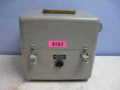
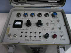
CV-3510/UG Signal Data Converter

cv3510-ug-test-53.jpg (26723 bytes)

I really need the manual - 
TM 11-5895-1370-12-3

Looks like it can operate on 220 or 110vac (400Hz), or 28vdc
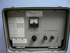
cv3510-ug-test-54.jpg (26230 bytes)

Not clear what these connectors usually go to.
cv3510-ug-test-52.jpg (13861 bytes)
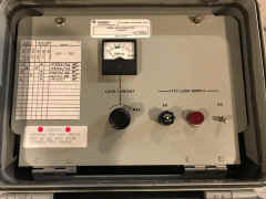
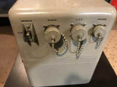
Looks like a portable test unit, but appears to be an actual TU.
cv3510-ug-test-51.jpg (13747 bytes)
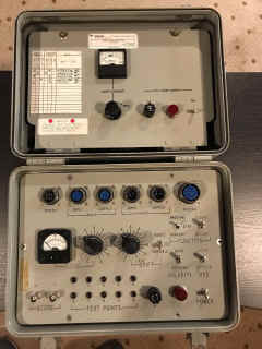
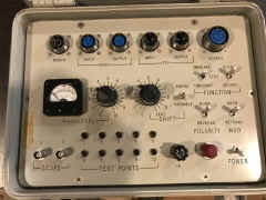
cv3510-test-1706-01.jpg (298459 bytes) Converter
cv3510-test-1706-02.jpg (248365 bytes)
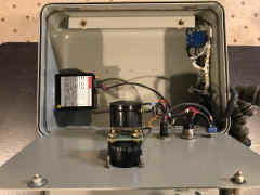
Loop supply
cv3510-test-1706-03.jpg (231858 bytes)
Loop supply with 28vdc to 120vdc converter
cv3510-test-1706-04.jpg (227614 bytes)
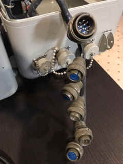
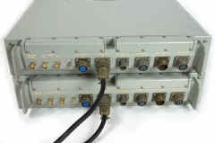
cv3510-test-1706-05.jpg (214325 bytes) The connectors shown on the left come from the case lid and plug into the Converter's receptacles shown above. They route these signals to the external connectors shown on the right. The unit can then be used while sealed up.

cv3510-1706-21.JPG (1876908 bytes)

cv3510-test-1706-07.jpg (169292 bytes) cv3510-1706-20.JPG (1643021 bytes)
Loop supply with 28vdc to 115vdc converter
cv3510-1706-22.JPG (1368919 bytes)
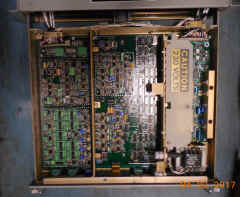
Converter front panel removed
cv3510-1706-23.JPG (1747058 bytes)
Rear of front panel - shielded I/O connectors
cv3510-1706-24.JPG (2154828 bytes)
28vdc to 115vac 400 Hz converter at right.
cv3510-1706-25.JPG (1859054 bytes)
Why these wires???
cv3510-1706-26.JPG (1923353 bytes)
Four stacked circuit boards
cv3510-1706-27.JPG (1611519 bytes)
Fuses and Voltage Selector
cv3510-1706-28.JPG (1426749 bytes)
Circuitry bolted to heat sink at bottom
cv3510-1706-29.JPG (2134987 bytes)

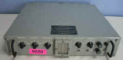
CV-3510A/UG
(part of AN/URA-17E)

cv3510-ug.JPG (93327 bytes)

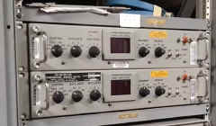
AN/URA-17E diversity system comprises two CV-3510A

AFSK Terminal Unit
(converter and keyer)

VLF= 1000 Hz mark / 1050Hz space
LF= 915Hz mark / 1085Hz space
HF= 1575Hz mark / 2425Hz space
UHF= 500Hz mark / 700Hz space
MMM= 1615Hz mark / 1785Hz space

AN/URA-17E aboard BB-61
DSC02084.JPG (3867656 bytes)

Manuf Gould Navcom

Manual is EE162-AH-OMI-010/E110 URA17E - manual

URA-17E specs
URA-17E connections

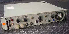
CV-3510B/UG
(part of AN/URA-17F)

ura17f-61.jpg (9897 bytes)

ura17f-63.jpg (7242 bytes)

AFSK Terminal Unit
(converter and keyer)

VLF= 1000 Hz mark / 1050Hz space
LF= 915Hz mark / 1085Hz space
HF= 1575Hz mark / 2425Hz space
UHF= 500Hz mark / 700Hz space
MMM= 1615Hz mark / 1785Hz space

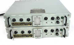
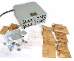
AN/URA-17F diversity system comprises two CV-3510B

cv3510b-ug-01.JPG (43188 bytes)

ura17f-62.jpg (15946 bytes)
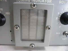
LED tuning indicator

manual NAVSHIPS 0967-LP-340-0010 Technical Manual for Comparator- Converter Group AN/URA-17F
Operating info (630kb pdf) 

cv3510b-1612-01.jpg (176462 bytes) cv3510b-1612-02.jpg (204117 bytes) cv3510b-1612-03.jpg (271822 bytes) cv3510b-1612-04.jpg (147735 bytes)
ura17f-1911-01.JPG (7058040 bytes) Input switch - 
  Left - high level neutral (60ma loop)
  Mid - high level polar (20 ma loop)
  Right - low level polar (+/-6v)
ura17f-1911-02.JPG (6082987 bytes)
ura17f-1911-04.JPG (5706759 bytes) Toggle switch
     Left - Secure/sync mode
Rocker switches
     Left - "back-to-back" mode
ura17f-1911-03.JPG (5757038 bytes)

CV-3510C/UG
(part of AN/URA-17G)

cv3510c-ura17g-1702-01.jpg (864856 bytes)

cv3510c-ura17g-1702-02.jpg (4297385 bytes) Appears similar to CV-3510B
LED indicator bars

Please send e-mail if you have a manual that I can buy or borrow to scan

AN/URA-17G diversity system comprising two CV-3510C aboard USS New Jersey

cv3510c-bb62-01.jpg (219218 bytes)

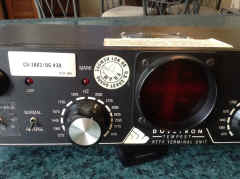
CV-3883/UG (Dovetron MPC-1000CR/T) TEMPEST 
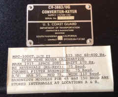
cv3883-dovetron-1701-01.jpg (615245 bytes)

   Manual

   Info on freq shifts   

cv3883-dovetron-1701-04.jpg (525374 bytes)

cv3883-dovetron-1701-03.jpg (725767 bytes) cv3883-dovetron-1701-02.jpg (279586 bytes)

MD-1061(V)/USC Digital Modem

DSC02110.JPG (3954775 bytes) DSC02104.JPG (3845097 bytes) p1010051.jpg (57931 bytes)

TH-20/UG

th20-ug-01.jpg (1892420 bytes)

th20-ug-02.jpg (2950520 bytes) th20-ug-03.jpg (568304 bytes) Manuf H.O. Boehme Type 6-C

NAVSHIPS 92484

manual pdf

Harris RF-3352

rf3352_5428.JPG (1564255 bytes)

rf3352_5431.JPG (1530672 bytes)

270-3400 Hz center
+/- 0-597.5 Hz shift
50-150 baud 

Neutral/Polar Loop input/output
internal loop supply
RS-232C input/output

Autostart relay
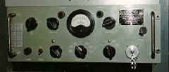
rf3352_5429.JPG (5163042 bytes) rf3352_5430.JPG (5495171 bytes)

 SGC-1 has 2 connectors on chassis with cables running to a terminal strip in the case:

 CONNECTOR   TERMINAL
 STRIP   
 SIGNAL     COLOR             CONNECTOR   TERMINAL
 STRIP   
 SIGNAL     COLOR
 J108 (7 pin)                J107 (8 pin)         
 A     5     AF IN     BLK  A     7     TTY     BLK
 B     6     AF IN     YEL  B     8     TTY     YEL
 C     3     AF OUT     BLK  C     2     115vac     RED
 D     4     AF OUT     RED  D     1     115vac     GRN
 E      9     ???     YEL  E      12     ground     RED (control?)
 F     10     ???     BLK  F     11     control?     BLK
 G     -     -     -  G     case     ground     WH/BLK
               H     -     -    -

AN/AGA-1 Airborne Audio TU system

2275 cps Space, 2475 cps Mark Audio FSK adapter - 
"used in conjunction with any voice-modulated
transmitter and receiver"

Includes 

  • TT-30/AGA-1 Teletypewriter
    (Teletype Model 31)
  • TT-31/AGA-1 Terminal Unit 

Please send me e-mail  if you have a photo, manual, 
more info, etc. on the TT-31/AGA-1 

TT-30/AGA-1 manual is here 

TT-30-1.jpg (65576 bytes) TT-30-2.jpg (47289 bytes) aga1-spec.JPG (1385349 bytes)