Navy Receiving Antenna Multicouplers

NRL Development of Receiver Multicouplers

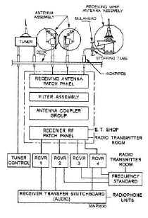
Shipboard Receiver RF Distribution
1950's Shore Station Receiver RF Distribution
Normal Receiver Site RF Distribution
rcvr-ant-81.JPG (97823 bytes)
CDAA Receiver Site RF Distribution
rcvr-ant-92.JPG (137677 bytes)

More Info on AN/FRD-10 CDAA System

- -

RECEIVING ANTENNA COUPLERS & MULTICOUPLERS
Note - multicouplers that are part of AN/FRD-10 CDAA system are listed here

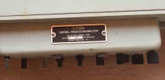
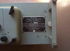
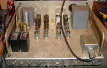
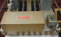
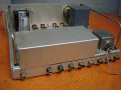
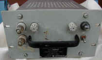
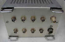
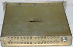
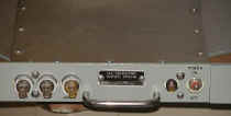
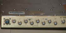
NT-50172

ckb50172-01.JPG (89825 bytes)


ckb50172-02.JPG (74093 bytes)

4-24 mc - 4 outputs

ckb50172-03.JPG (63007 bytes)

ckb50172-04.JPG (89637 bytes)

Manuf Hoffman
NAVSHIPS 900,226 
- download 7.9 MB pdf - thanks to AWA

NT-50279

RXA

rxa-spec-01a.JPG (101823 bytes) 4-24mc, 3 antenna inputs, up to 10 receivers on each
Uses NT-50279 multicoupler

rxa-spec-01.JPG (235437 bytes)

rxa-spec-02.JPG (146268 bytes)

Manuf Hoffman

NAVSHIPS 900213

AN/SRA-9
AN/SRA-12

sra12-01.jpg (75717 bytes)

sra12-01.JPG (66109 bytes)

p1010055.jpg (58959 bytes)
SRA-12 on board BB-62

sra12-101.JPG (84921 bytes)

14kc-32mc - 7 channels

Electrical filter assemblies (multicouplers) AN/SRA-9 and AN/SRA-12 are identical in appearance and function. They are receiving antenna distribution systems that make possible the multiple operation of a maximum of 28 radio receivers from a single antenna. Ordinarily it is preferable, however, to limit the total number of receivers to seven.
    The AN/SRA-12 filter assembly provides seven radio frequency channels in the frequency range from 14 kc to 32 mc. Any or all of these channels may be used independently of any of the other channels, or they may operate simultaneously. Connections to the receivers are made by means of coaxial patch cords, which are short lengths of cable with plugs attached to each end.
    A set of nine plug-in type filter subassemblies is furnished with the equipment, but only six of them may be installed at one time. The six filters installed are selected to cover the seven most-used frequency bands. Filter crossover frequencies are 50, 150, 300, 530, 1500, 2000, 3500, 7000, and 14000 kc.

SRA-9 manual NAVSHIPS 91777
SRA-12 manual NAVSHIPS 92206

Manual pages - operation, schematics, etc.

AN/SRA-24(XG-2)

sra24-1100.JPG (243226 bytes)

sra24-01.JPG (52028 bytes) Receiving Antenna Coupler -  3 antenna inputs (plus aux and calib), one rcvr output

Components:
  CU-746/SRR (2-6 MC)
  CU-747/SRR (5-15 MC)
  CU-748/SRR (11-32 MC)

- please send me e-mail with any info and photos

sra24-1102.JPG (176786 bytes)

sra24-1103.JPG (254603 bytes)

sra24-1101.JPG (351270 bytes) CU-748/SRR (11-32 MC) interior
sra24-207.JPG (219939 bytes)
sra24-209.JPG (79780 bytes)

AN/SRA-38,-39,-40
    (56 rcvrs 2-30 mc)
AN/SRA-49
   
(20 rcvrs 2-30 mc)
AN/SRA-49A
   
(20 rcvrs 2-30 mc)
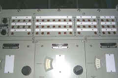
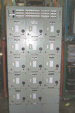
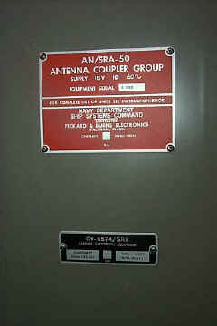
AN/SRA-50
    (14 rcvrs 2-30 mc)

Components

  • CU-1799/SRA (2-6 mc)           
  • CU-1800/SRA (4-12 mc)
  • CU-1801/SRA (10-17 mc)       
  • CU-1802/SRA (17-30 mc)
  • PP-4846/SRA power supply 
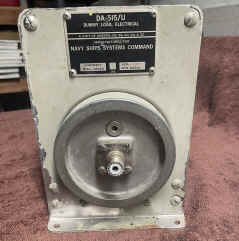
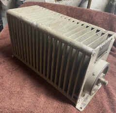
  • DA-515/U dummy load
  • SB-3332/SRA patch panel        
  • SB-3333/SRA patch panel
 

sra49-01.JPG (190075 bytes)

ANTENNA   COUPLER   GROUPS - These  groups  are  designed  to  connect  up to 20 MF and HF receivers to a single antenna, with a highly selective  degree  of  frequency  isolation.  Each  of  the six  coupler  groups  consists of  14  to  20  individual antenna  couplers  and  a single power  supply  module, all are slide-mounted in a special electronic equipment rack.  An  antenna  input  distribution  line  termination (dummy  load)  is  also  supplied.  In  addition,  there  are provisions  for  patching  the  outputs  from  the  various antenna  couplers  to  external  receivers.

Manual NAVSHIPS  0967-303-8610 - Download manual pdf

sra50-7.jpg (24884 bytes)

sra50-10.jpg (25667 bytes)

sra49-102.JPG (27610 bytes)

sra50-1.jpg (28216 bytes) sra50-3.jpg (18599 bytes) sra50-5.jpg (25782 bytes)
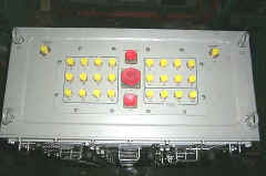
Top View

sra50-12.jpg (19040 bytes)

DA-515/U

Part of AN/SRA-38, -39, -40, -49, -50


da515-sra38-2307-01.jpg (408253 bytes) da515-sra38-2307-02.jpg (453124 bytes) ==

AM-4823/U Preselector/Multicoupler

am4823-02.JPG (324152 bytes)

am4823-01.JPG (1378093 bytes) 2-32 mc - allows receiver operation in high RF environments

used with DA-607/U dummy load & CU-1901/U antenna coupler (handles up to six AM-4823/U)

need better photos

Collins

0967-285-3010
download pdf

am4823-1407-01.jpg (223152 bytes) am4823-1407-02.jpg (229042 bytes) am4823-1407-03.jpg (190435 bytes) am4823-1407-04.jpg (159567 bytes)

CU-168/FRR

cu168-frr-101.jpg (11000 bytes)

cu168-frr-102.jpg (21008 bytes)

cu168-frr-01.JPG (118396 bytes)

cu168-frr-114.jpg (70281 bytes)

2-32 mc, 5 outputs, tube

technical article
Manuf Collins & others

cu168-frr-103.jpg (18378 bytes)

cu168-frr-113.jpg (52299 bytes)

Manual NAVSHIPS 91697A
Download

cu168-frr-104.jpg (22686 bytes)

cu168-frr-112.jpg (46888 bytes)

CU-656/U
CU-656A/U

cu656a-91.JPG (125624 bytes)

cu656a-u-1101.jpg (24785 bytes)

cu656-u-01.jpg (74522 bytes)
wrong meter

cu656-u-05.jpg (99425 bytes)
wrong connectors
2-32 mc, 8 outputs - tube
70 ohm in/out, type C connectors

CU-656A/U spec sheets

manual NAVSHIPS 93804 

Schematic

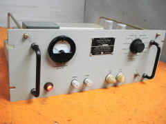
CU-872/U
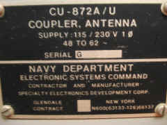
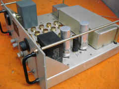
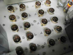
CU-872A/U

cu872a-u-01.jpg (20606 bytes)

cu872a-u-05.jpg (31130 bytes) cu872a-1310-01.jpg (265301 bytes) 2-32mc, 8 outputs - tube
70 ohm in/out, type N connectors

Diagram and circuit description

NAVSHIPS 93803(A)
CU-872/U manual 
NAVSHIPS 94490
CU-872A/U manual

cu872a-1310-04.jpg (284632 bytes) cu872a-1310-02.jpg (419194 bytes) cu872a-1310-03.jpg (434694 bytes) cu872a-1310-05.jpg (230228 bytes)

CU-873/U

need photo need photo like CU-656/U except type N connectors

CU-874/U

need photo need photo like CU-873/U except 150 ohm balanced input

CU-1099/FRR

cu1099-frr-01.jpg (27107 bytes) cu1099-frr-02.jpg (27653 bytes) 2-32 mc, 8 outputs - transistor
70 ohm in/out, type BNC connectors

Diagram and circuit description

NAVSHIPS 94933
avail from WA5CAB

CU-1280/FRD-10

cu1280-1307-05.jpg (54000 bytes)

cu1280-1307-04.jpg (71024 bytes) cu1280-1307-02.jpg (105230 bytes) cu1280-1307-01.jpg (113597 bytes)

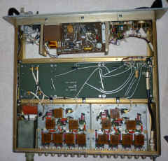
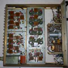
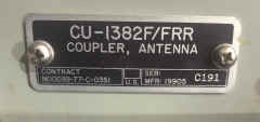
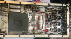
CU-1382/FRR

2-32 mc, 8 outputs - transistor
50 ohm in/out, type BN C connectors

thanks to Jim for CU-1382F photos

CU-1382C/FRR
cu1382c-1902-01.jpg (50017 bytes)
cu1382c-1902-02.jpg (249977 bytes) cu1382c-1902-04.jpg (482096 bytes)
cu1382f-2301-01.jpeg (516863 bytes) cu1382f-2301-03.jpg (5186961 bytes) cu1382f-2301-02.jpeg (884408 bytes)
cu1382f-2301-05.jpeg (2356883 bytes) cu1382f-2301-06.jpeg (2244879 bytes) cu1382f-2301-07.jpeg (2171110 bytes)
CU-1382G/FRR
cu1382h-frr-01.jpg (7196 bytes)
cu1382h-frr-03.jpg (7933 bytes) ==

CU-1423/U

cu1423- FRONT.JPG (520331 bytes)

cu1423-GUTS.JPG (756203 bytes) cu1423- STRIP.JPG (714124 bytes)

cu1423-STRIP-GUTS.JPG (660095 bytes)

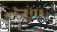
30-300 mc multicoupler
6 outputs

Spec Sheet

Photos thanks to WB2GCR

CU-1563/URR
CU-1574/URR
CU-1575/URR

nrl-multi-04a.JPG (117953 bytes) 10 receivers

CU-1563 2-6 mc
CU-1574 6-18 mc
CU-1575 10-30 mc

See NRL development page for info

spec sheet

CU-2007/SRR

cu2007srr-11.jpg (29062 bytes) Combiner-Multicoupler 

8 VLF-LF outputs 10kc-1.85mc

1 HF output 1.85mc-30mc

    More Photos & Info

CU-2065/BRR

cu-2065-2.JPG (17417 bytes)


cu-2065-4.JPG (21680 bytes)
VLF-LF & HF outputs

cu-2065-1.JPG (20216 bytes)

cu-2065-3.JPG (24771 bytes)

CU-2268/URR

cu2268-4.jpg (42803 bytes) VHF and HF outputs    More Photos & Info

CU-5013/SRR

cu5013-21.JPG (144858 bytes) cu5013-19.JPG (225342 bytes) 2-30 mc - 6 outputs
TMC AM6-2/70U
70 ohm in/out, type QC connectors

spec sheet

manual - thanks to K4OZY