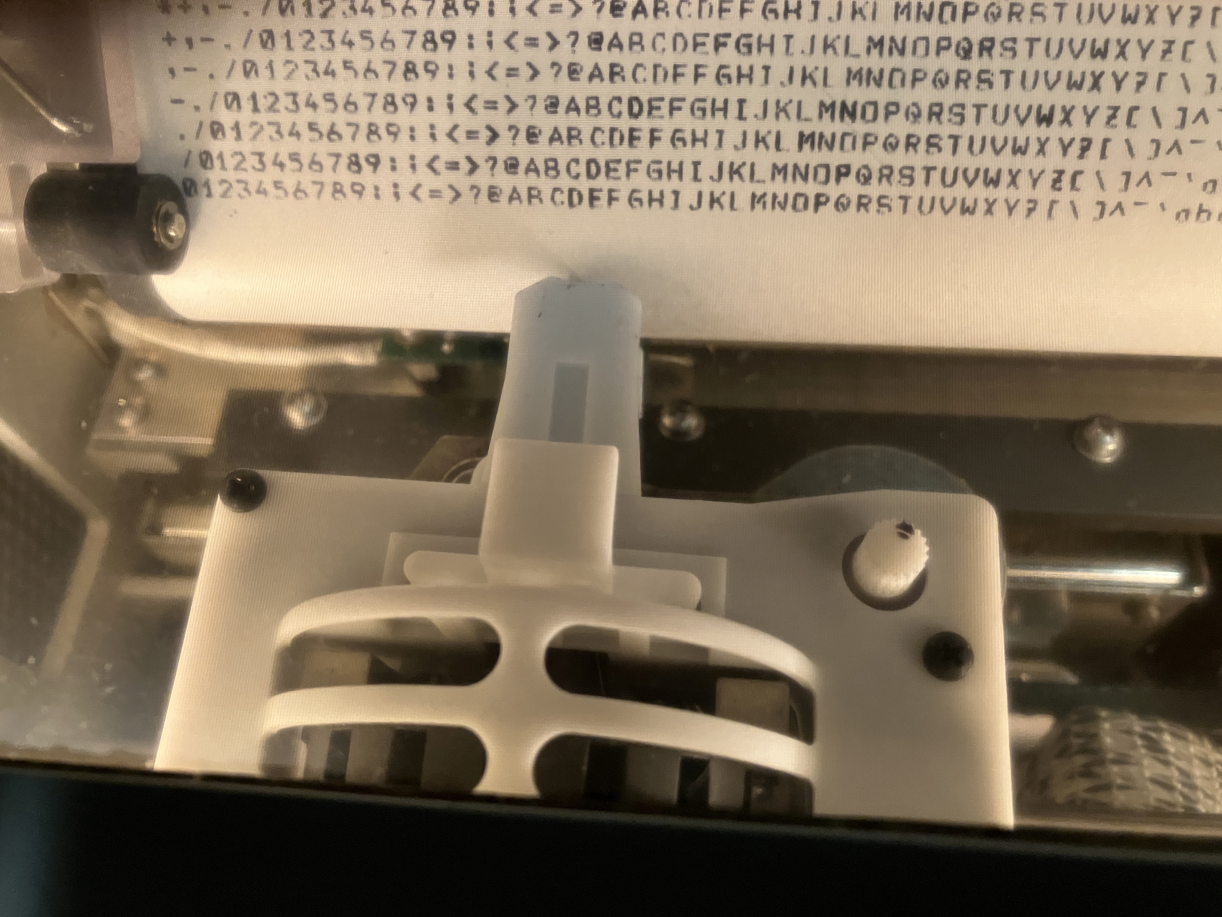
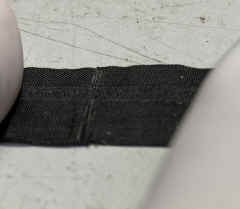
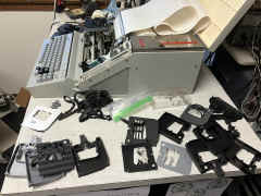
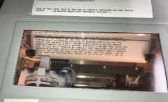
RIBBON: Cassette - black nylon tape, 16 yards long, 0.0045 thk, 0.52 in. wide, 75 rpm speed
Mfr NCR part no. 197939, E-systems dwg 69-00402-001
NSN 7510-01-297-6428
 |
 |
 |
 |
 |
 |
 |
 |
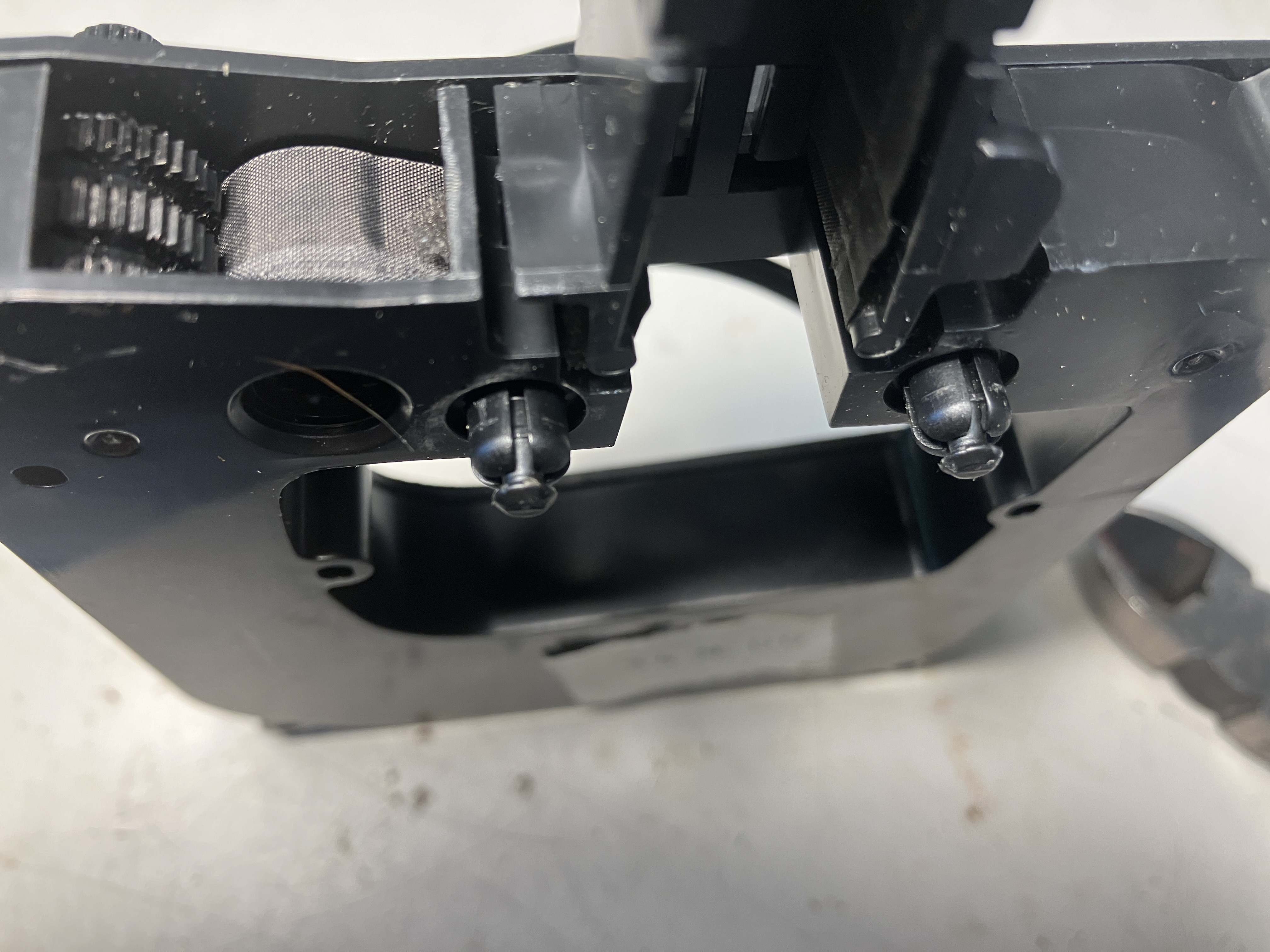
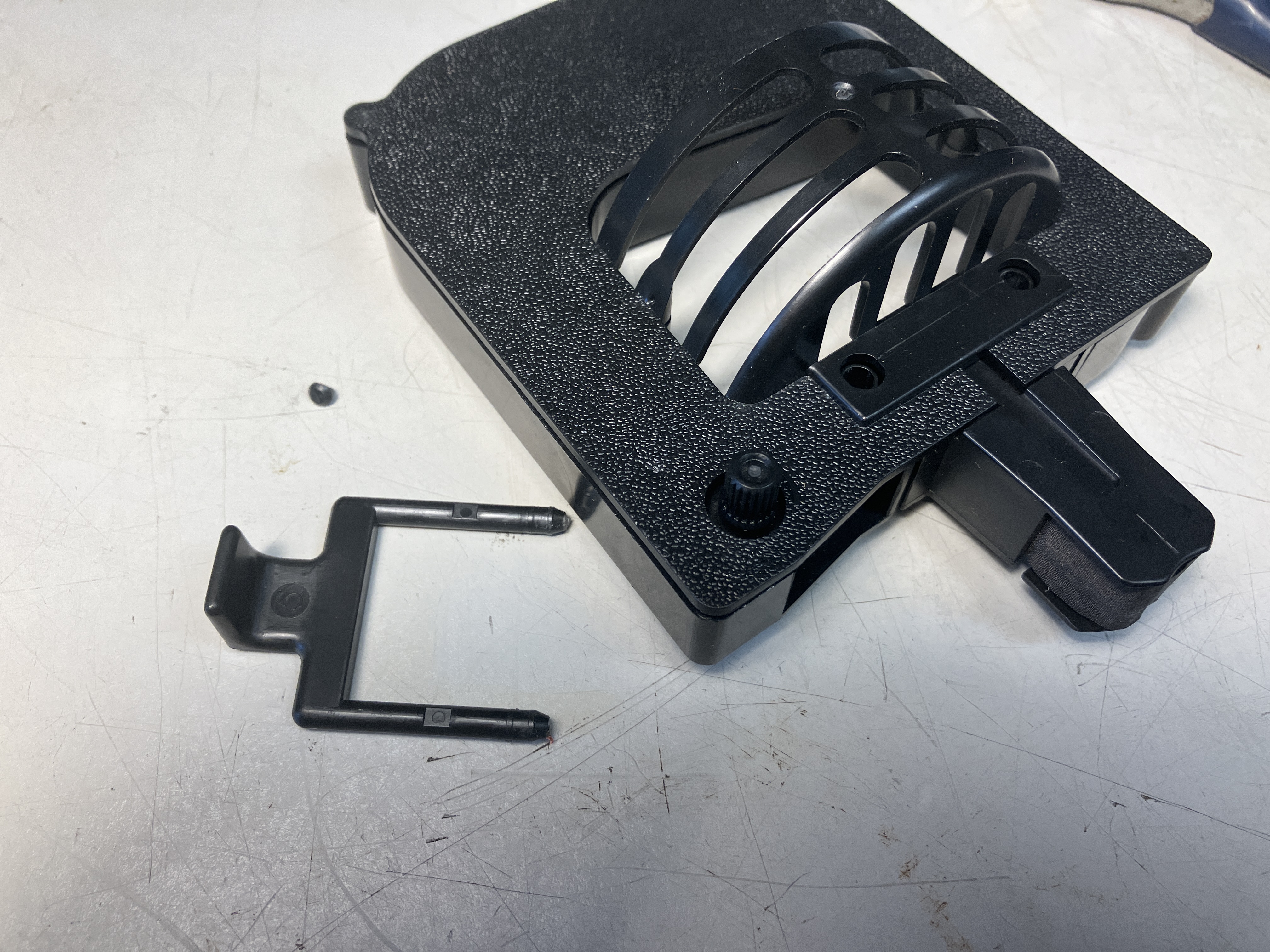
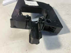
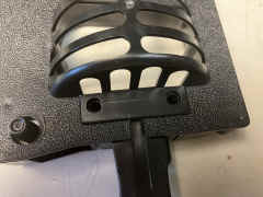
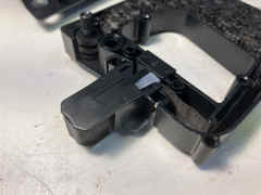
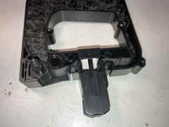
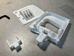
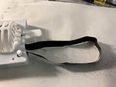
bottom - ends of lift handle are heated to mushroom
 |
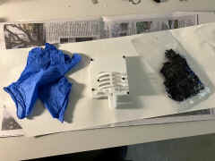
clipped the ends and removed lift hadle
 |
lift handle holes on top
 |
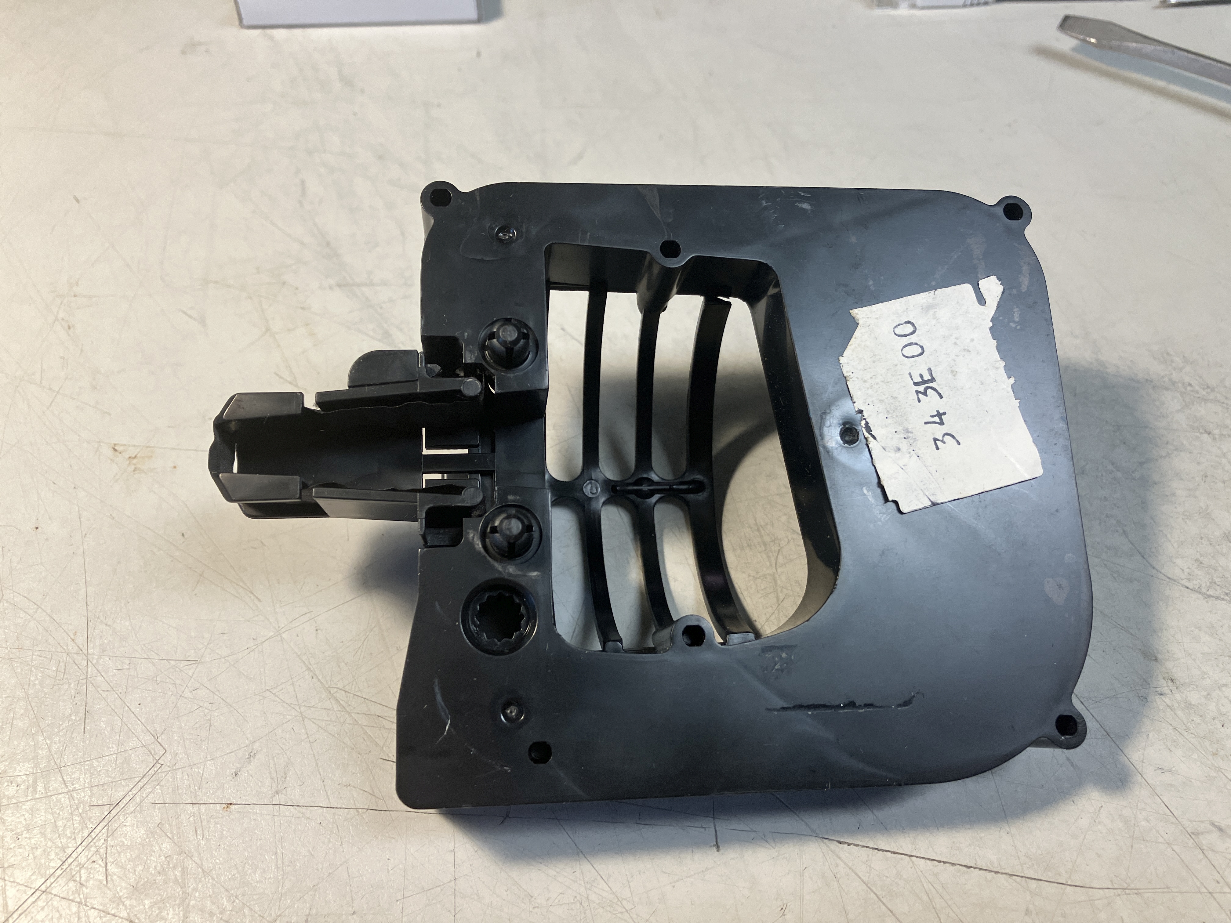
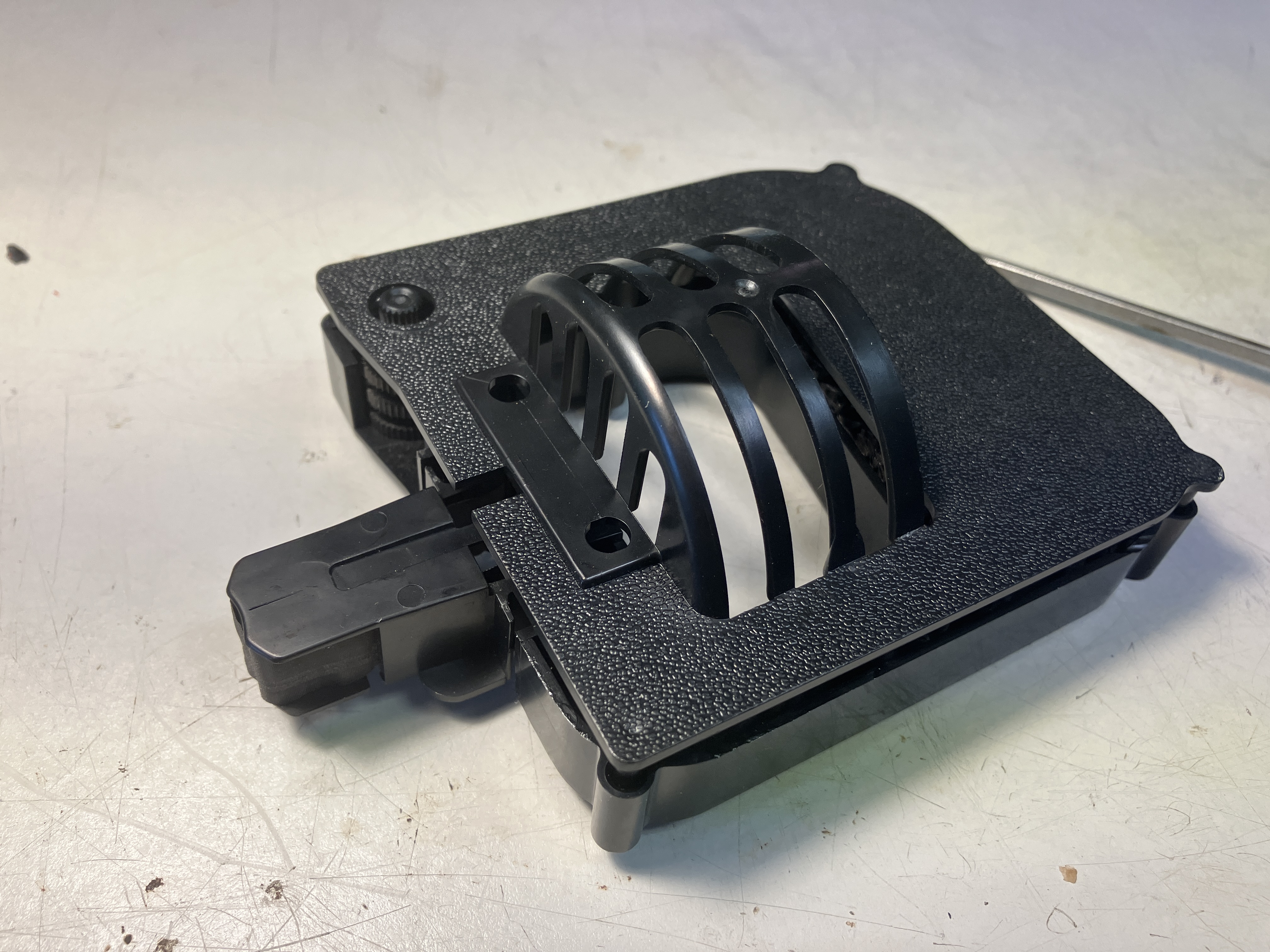
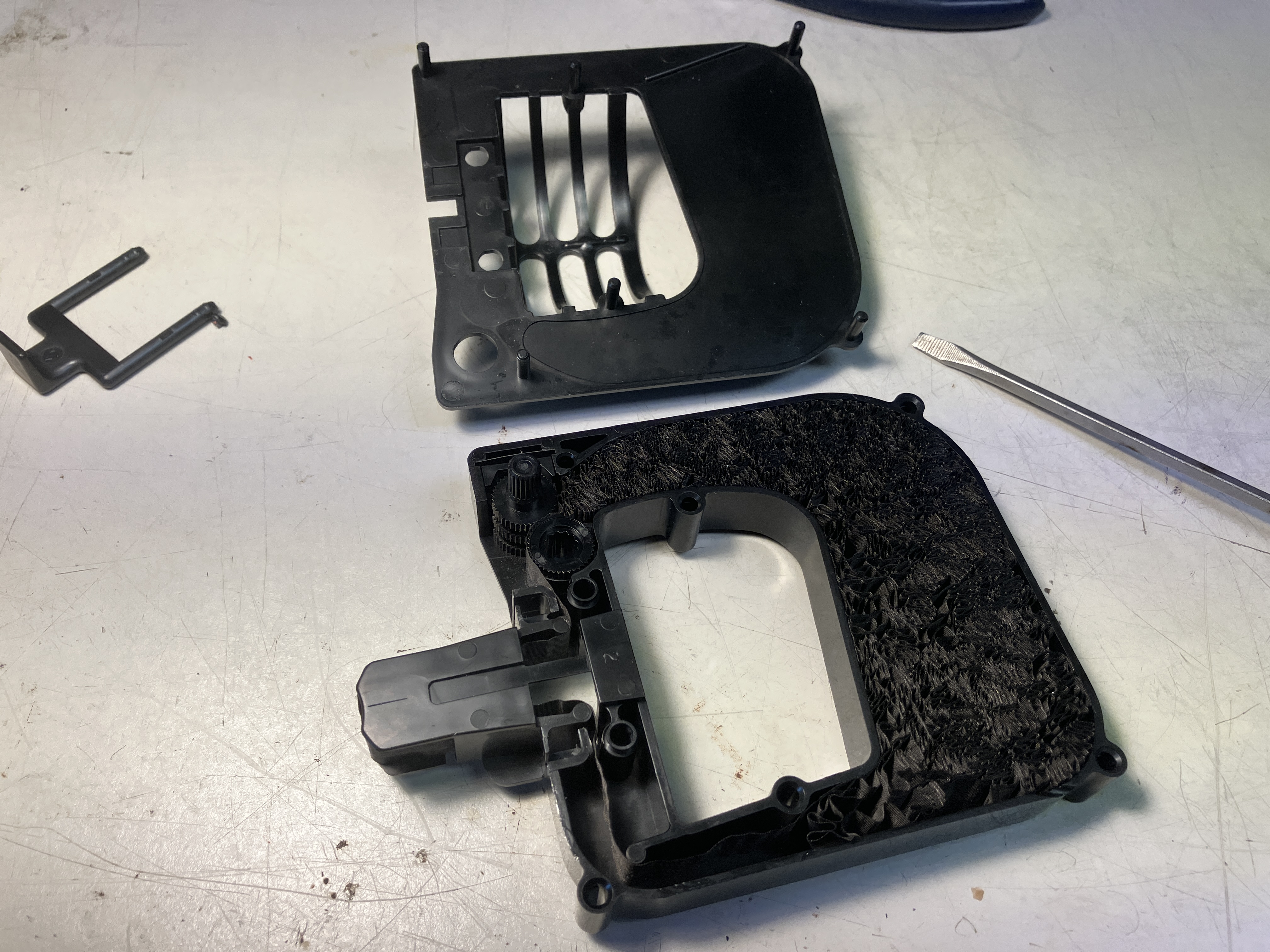
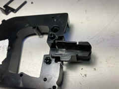
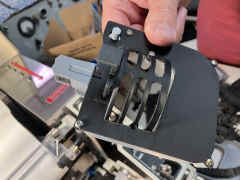
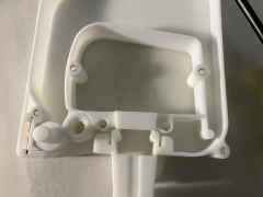
top is held on via 4 pins inserted into bottom
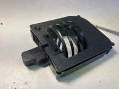 |
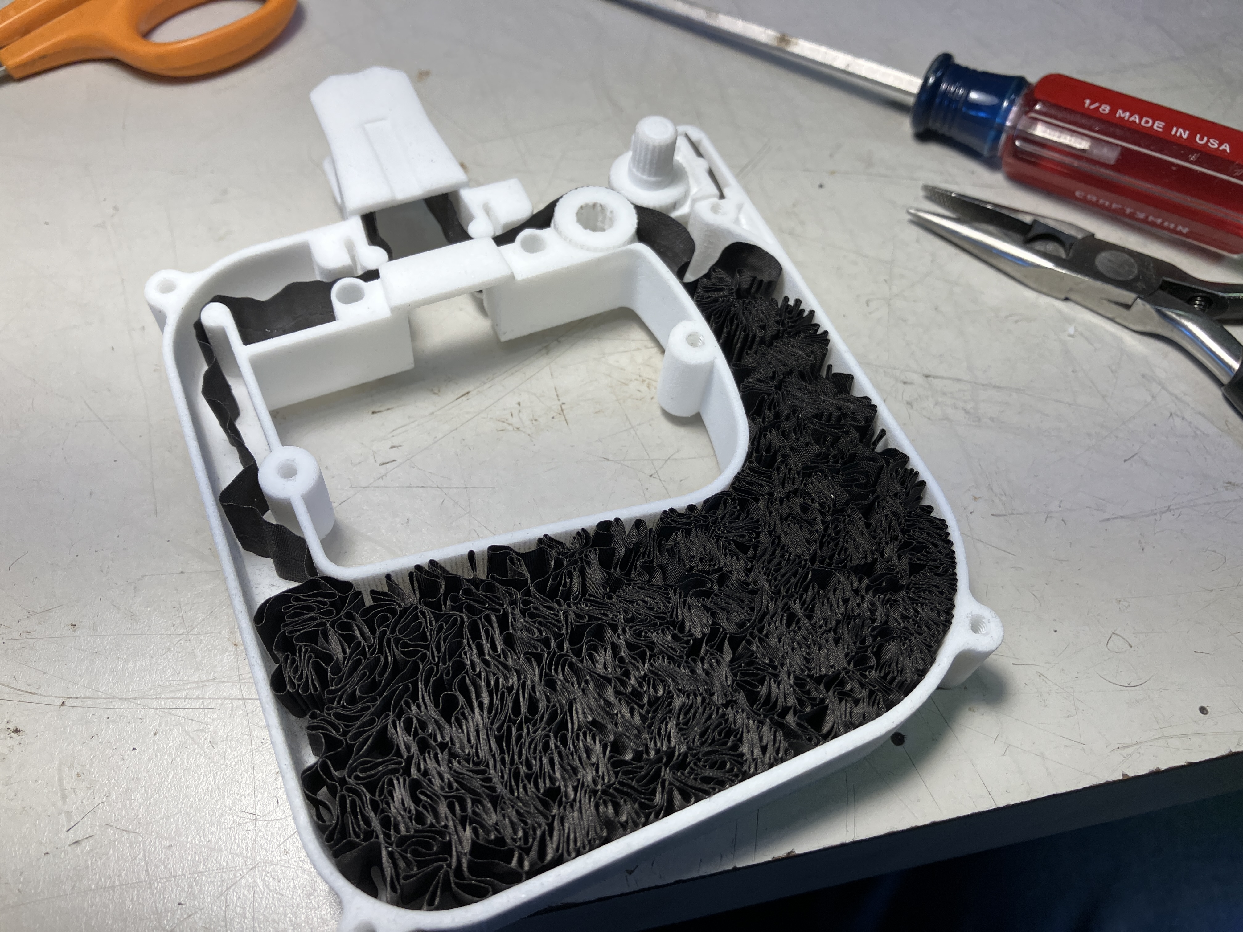
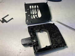
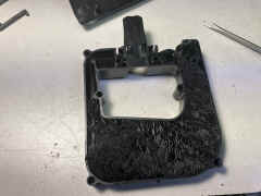
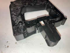
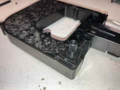
top removed
 |
 |
 |
 |
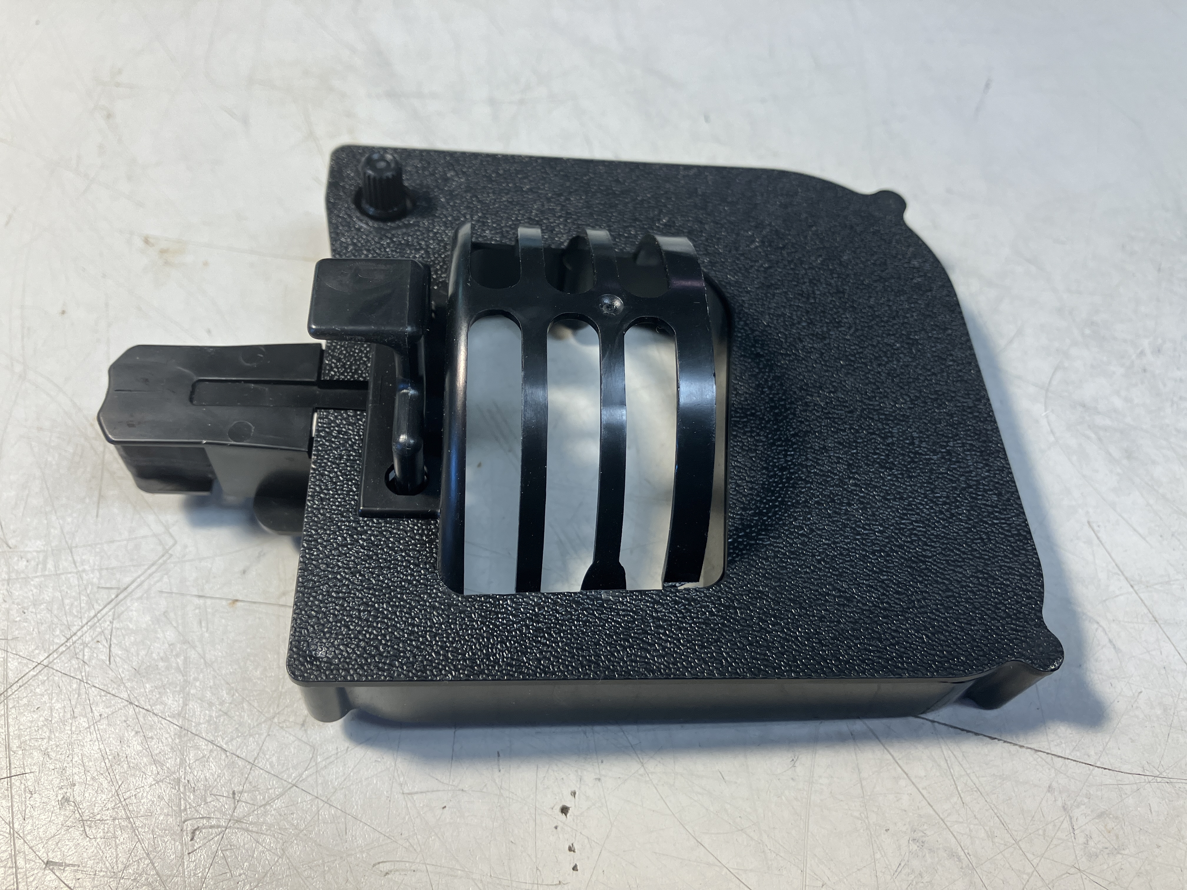
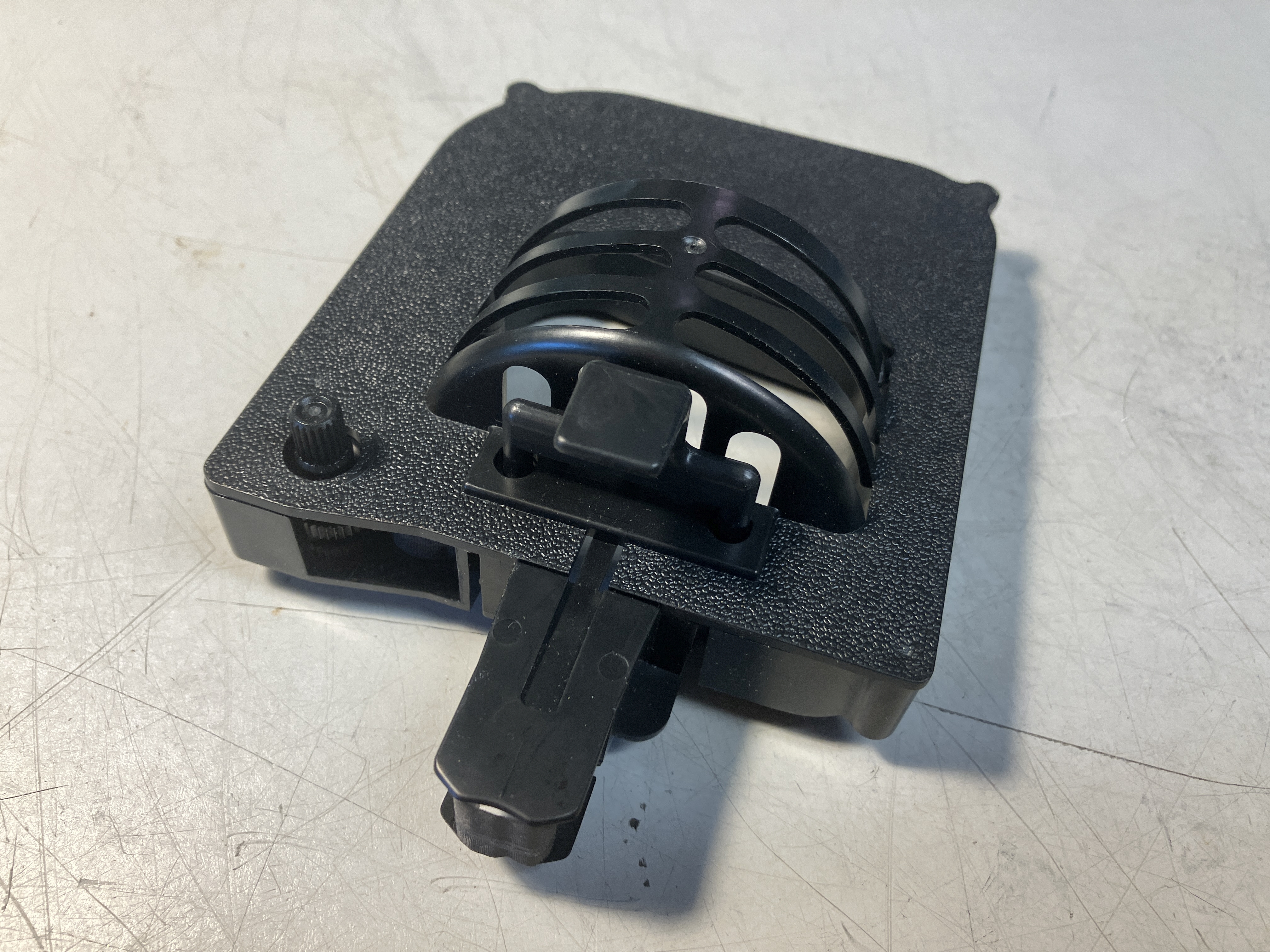
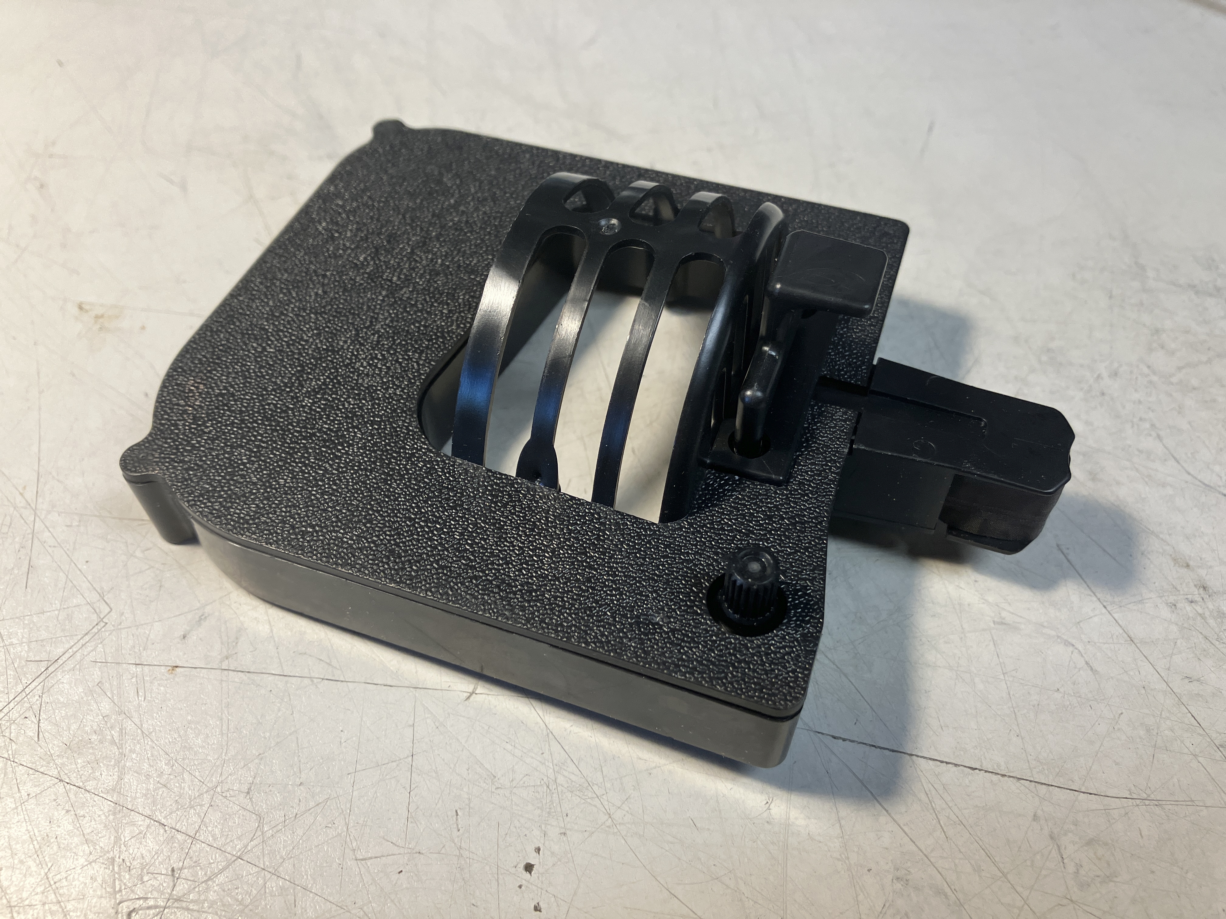
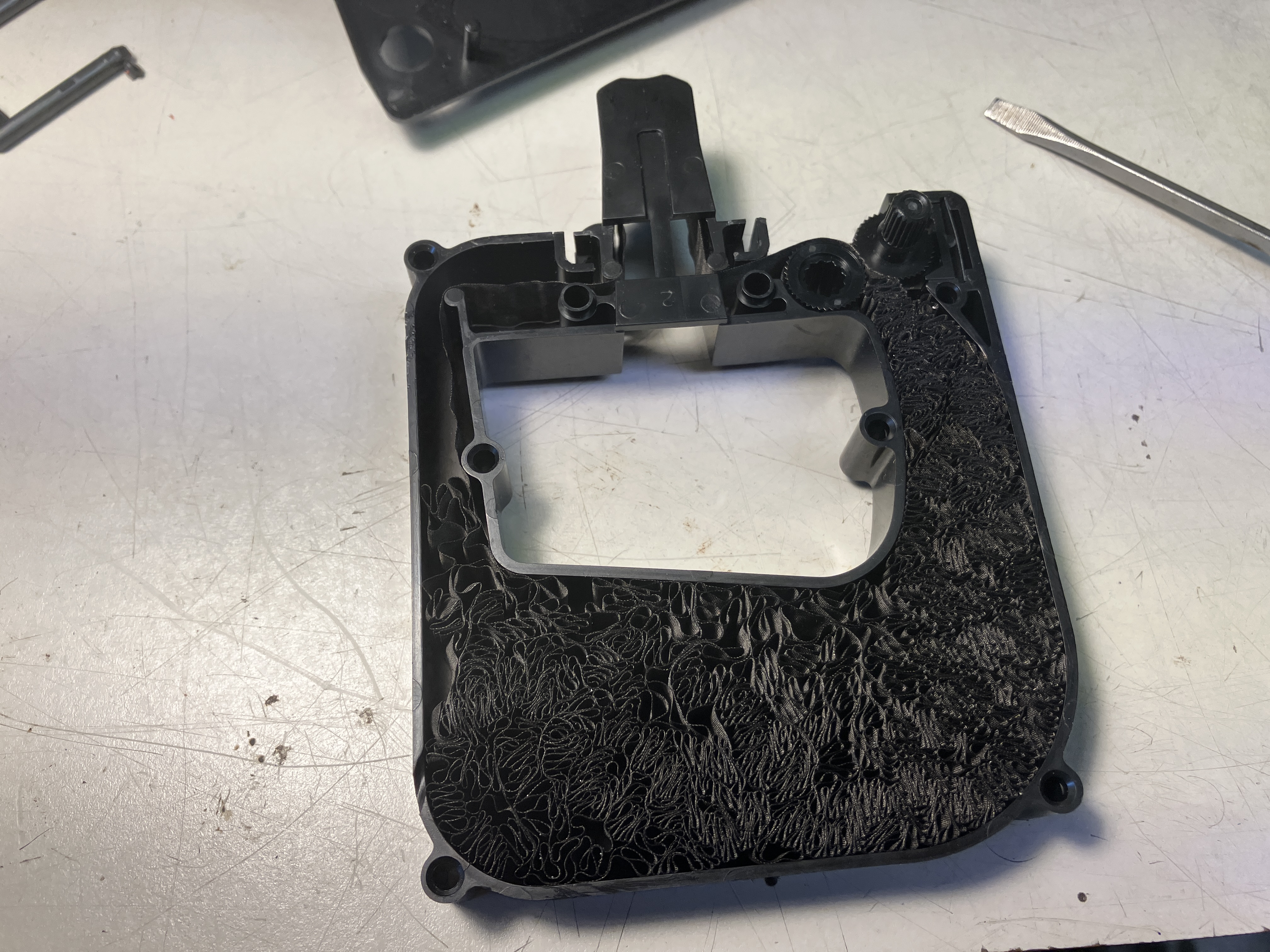
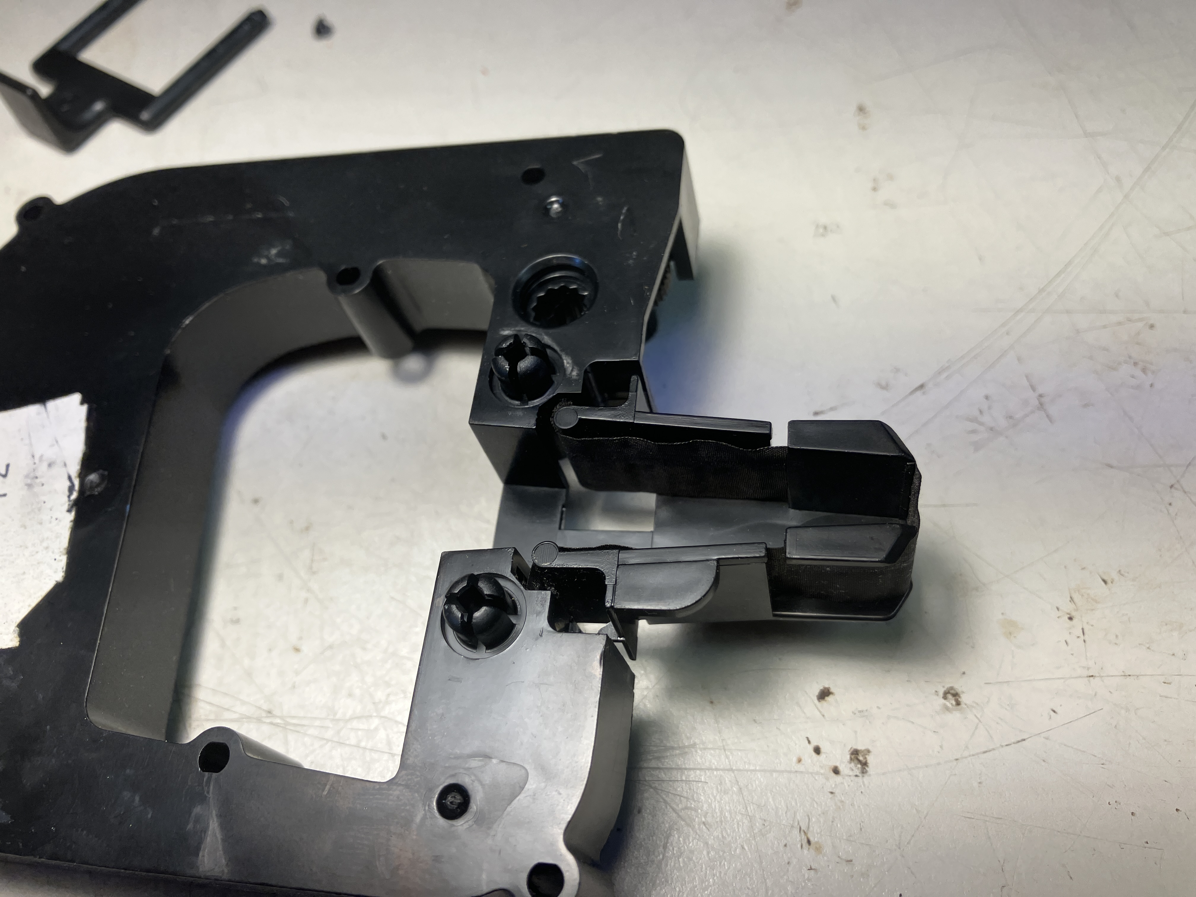
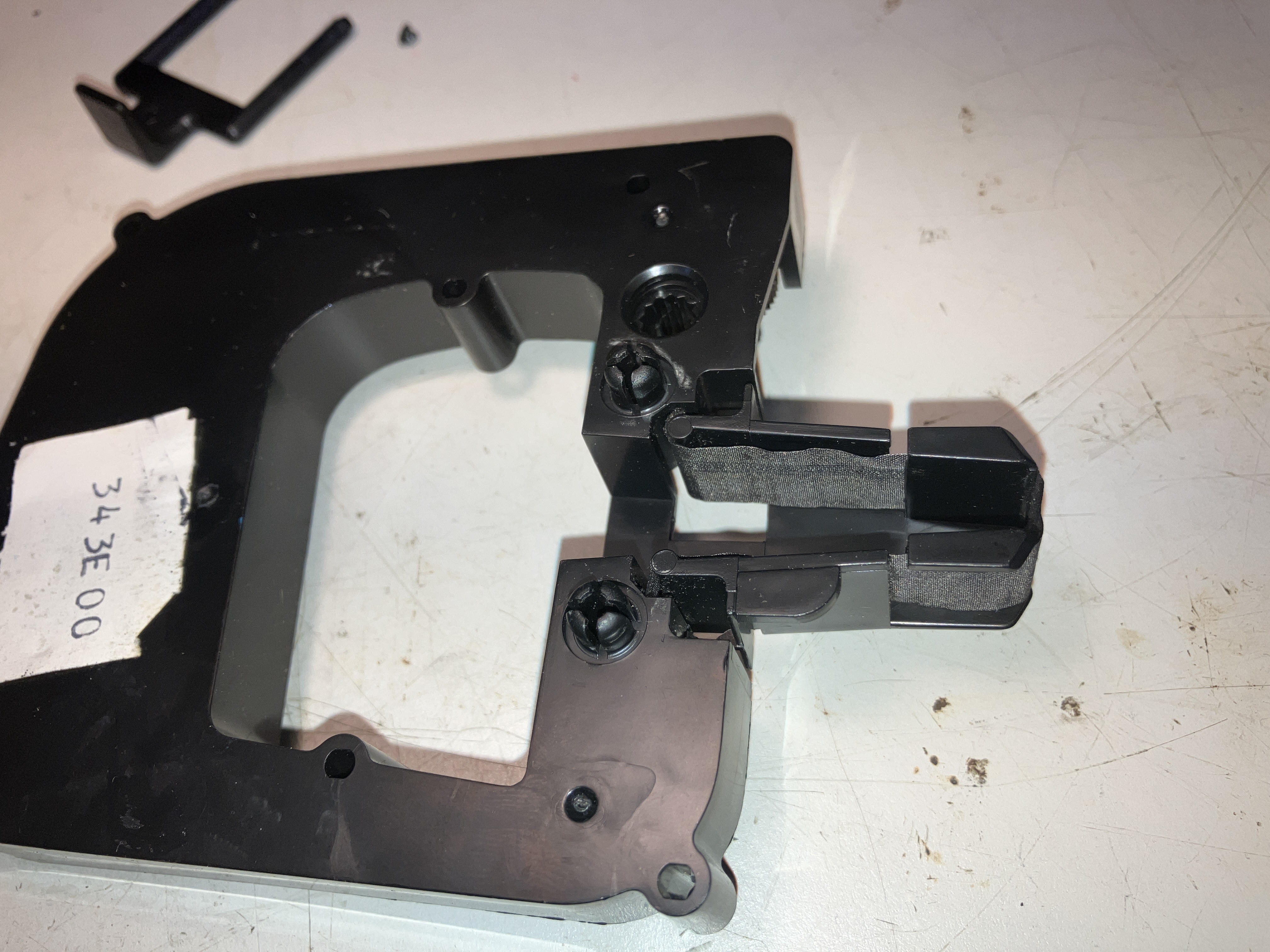
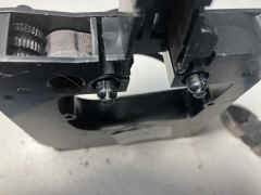
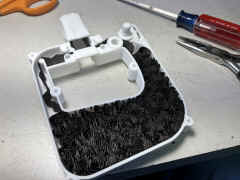
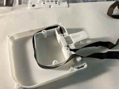
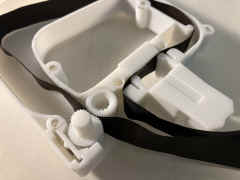
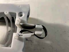
details of head - it is attached to the body via three small
flexible strips to let it "float"
 |
 |
 |
 |
 |
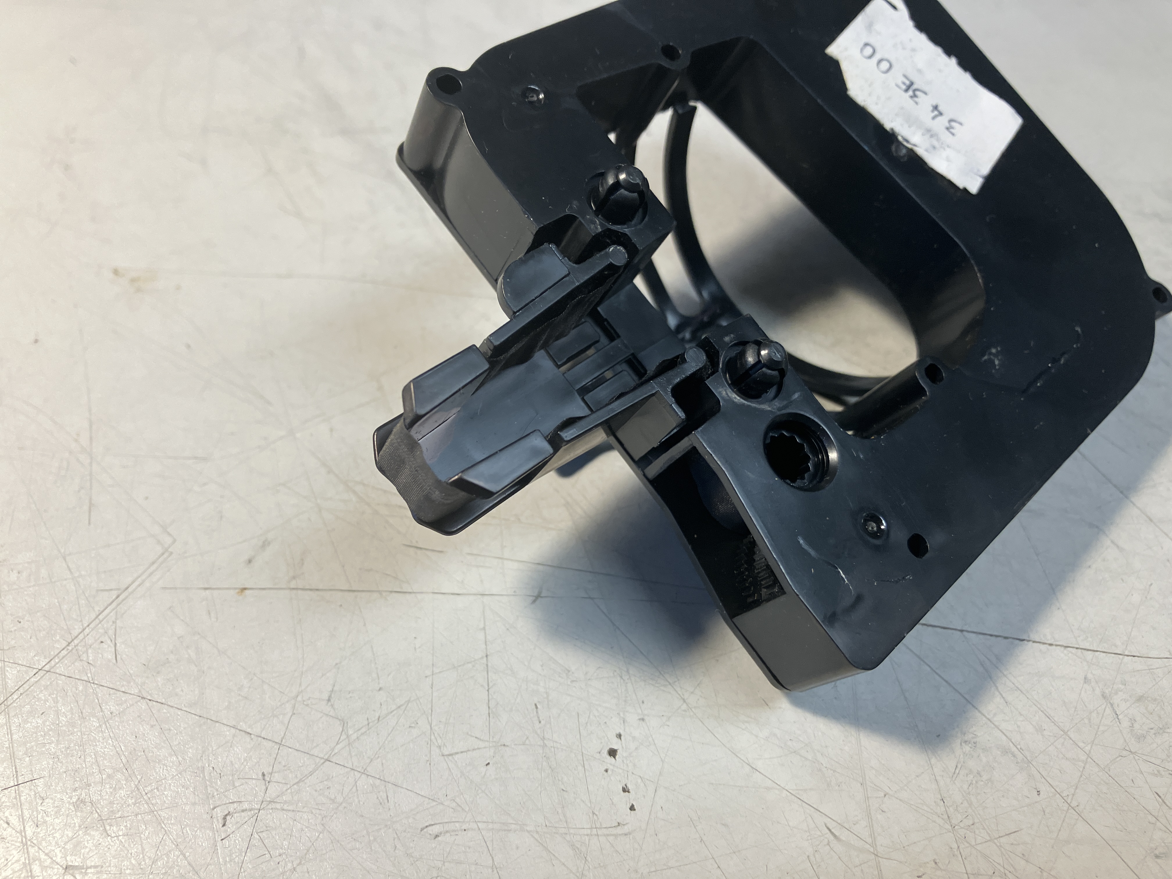
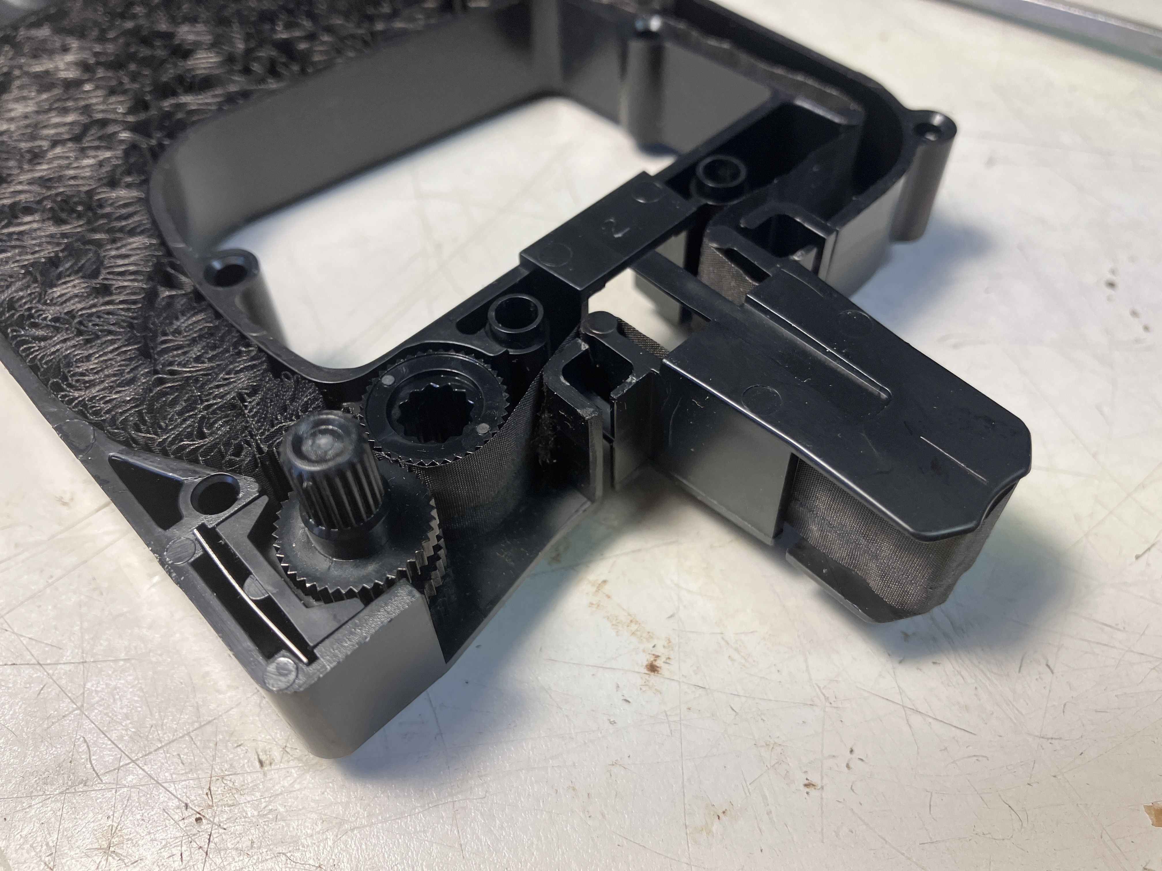
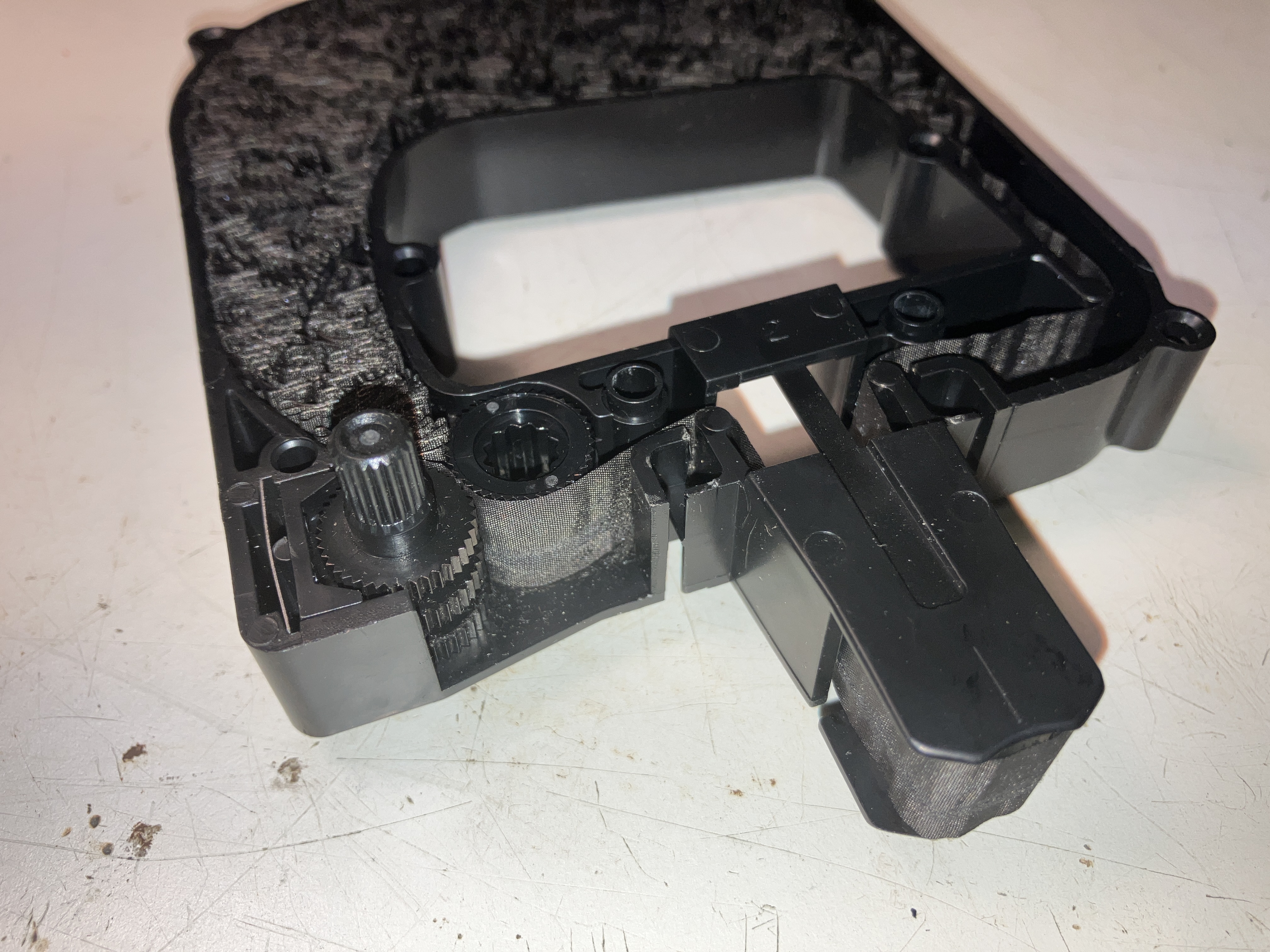
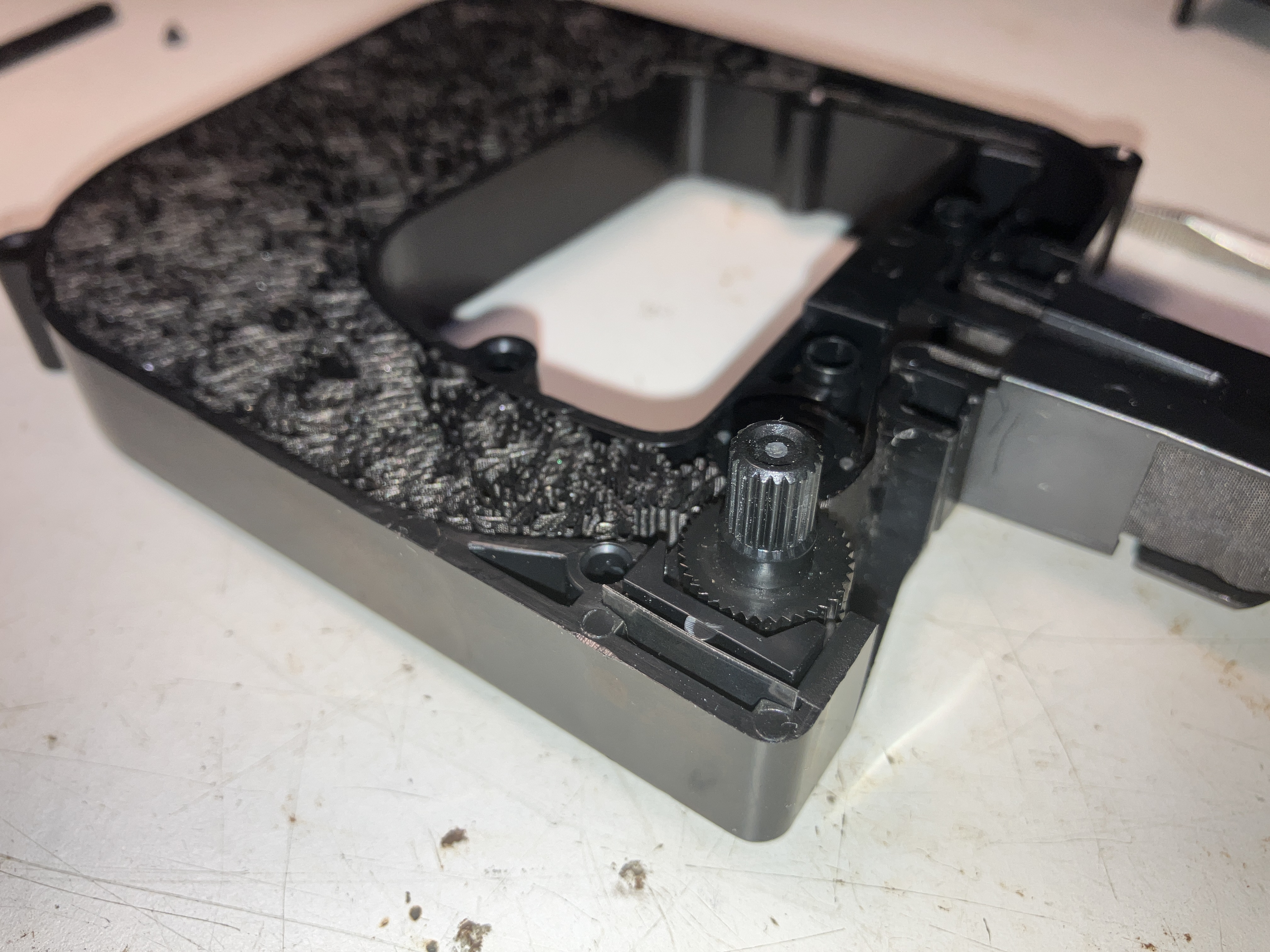
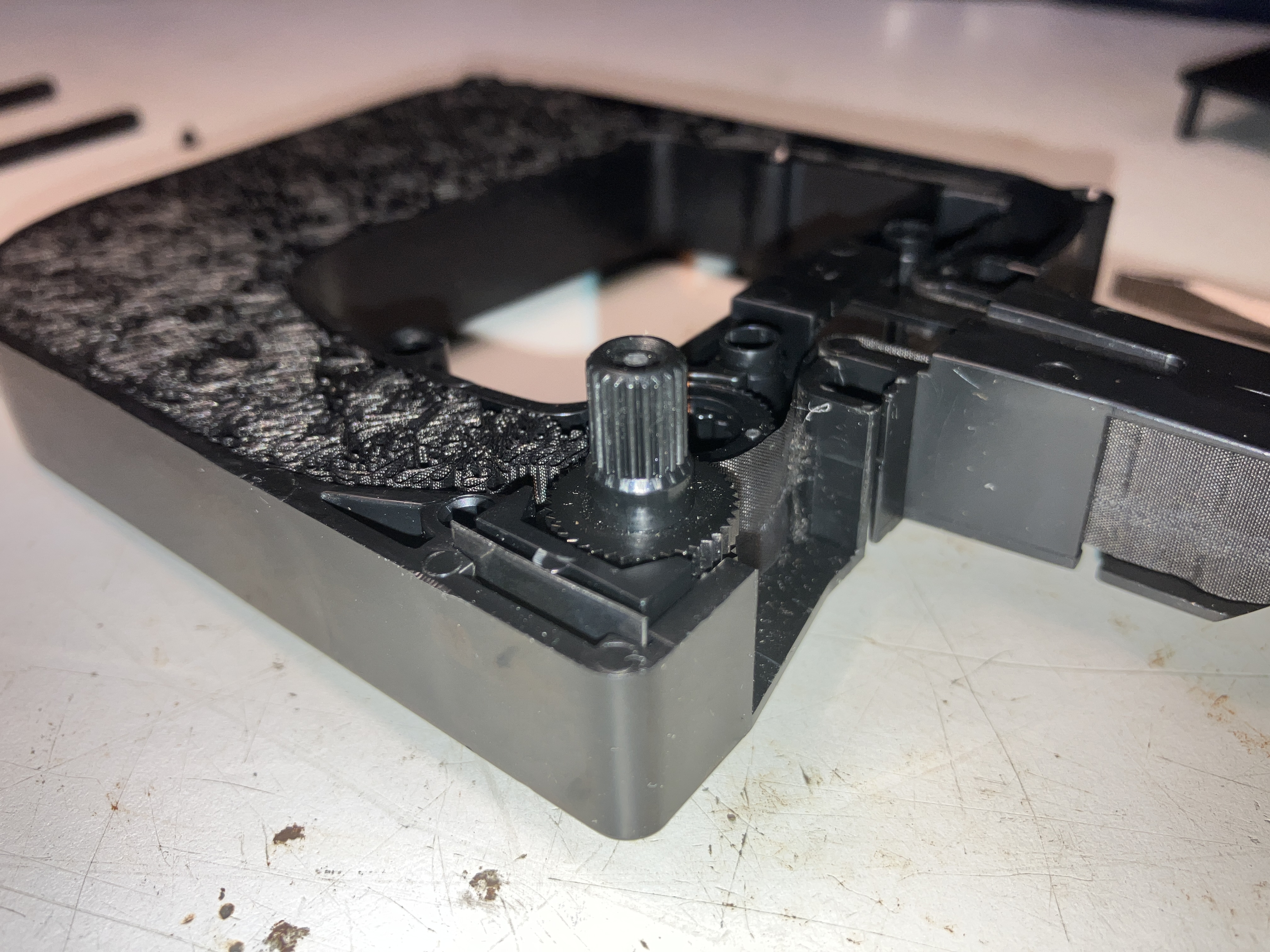
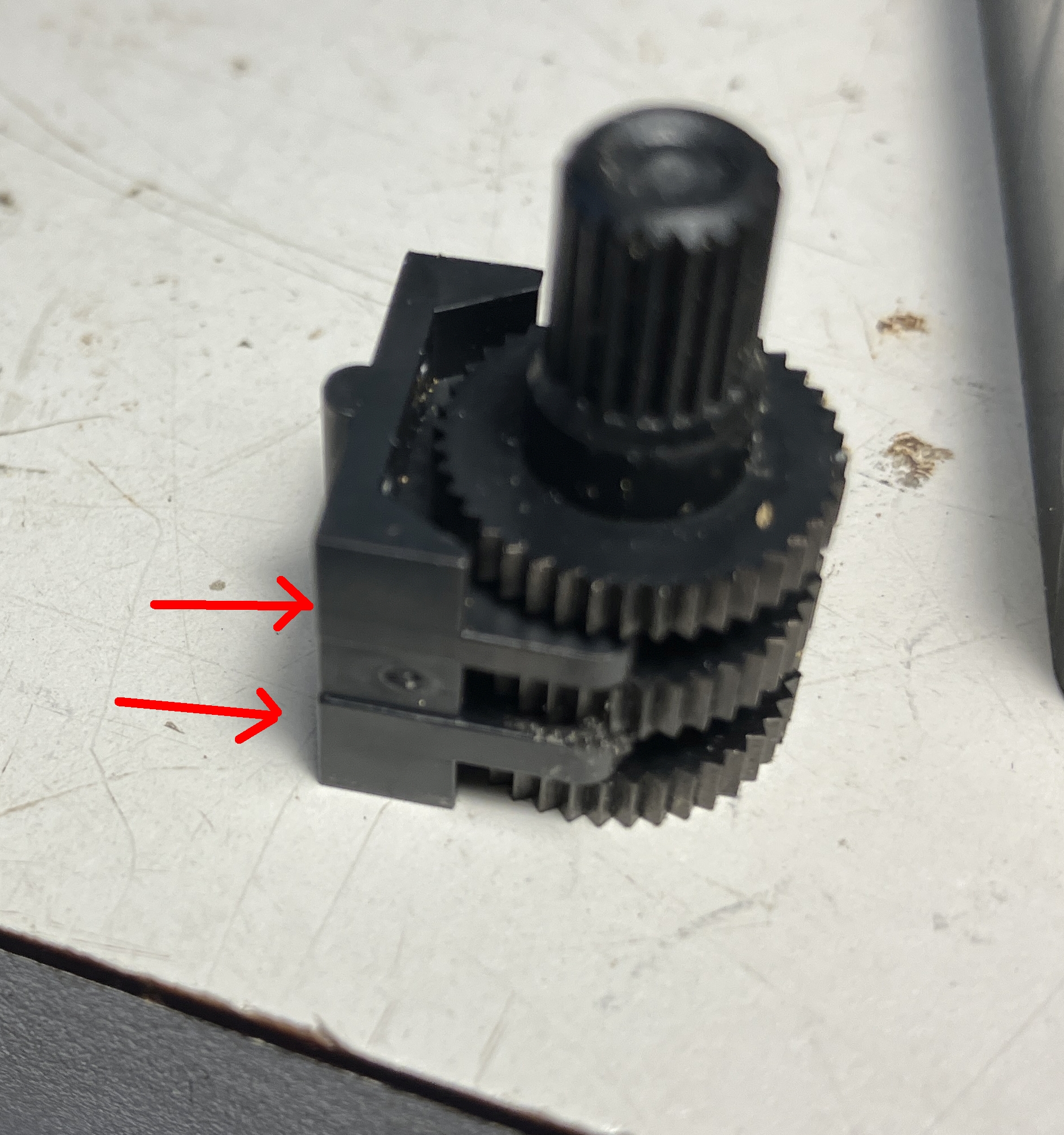
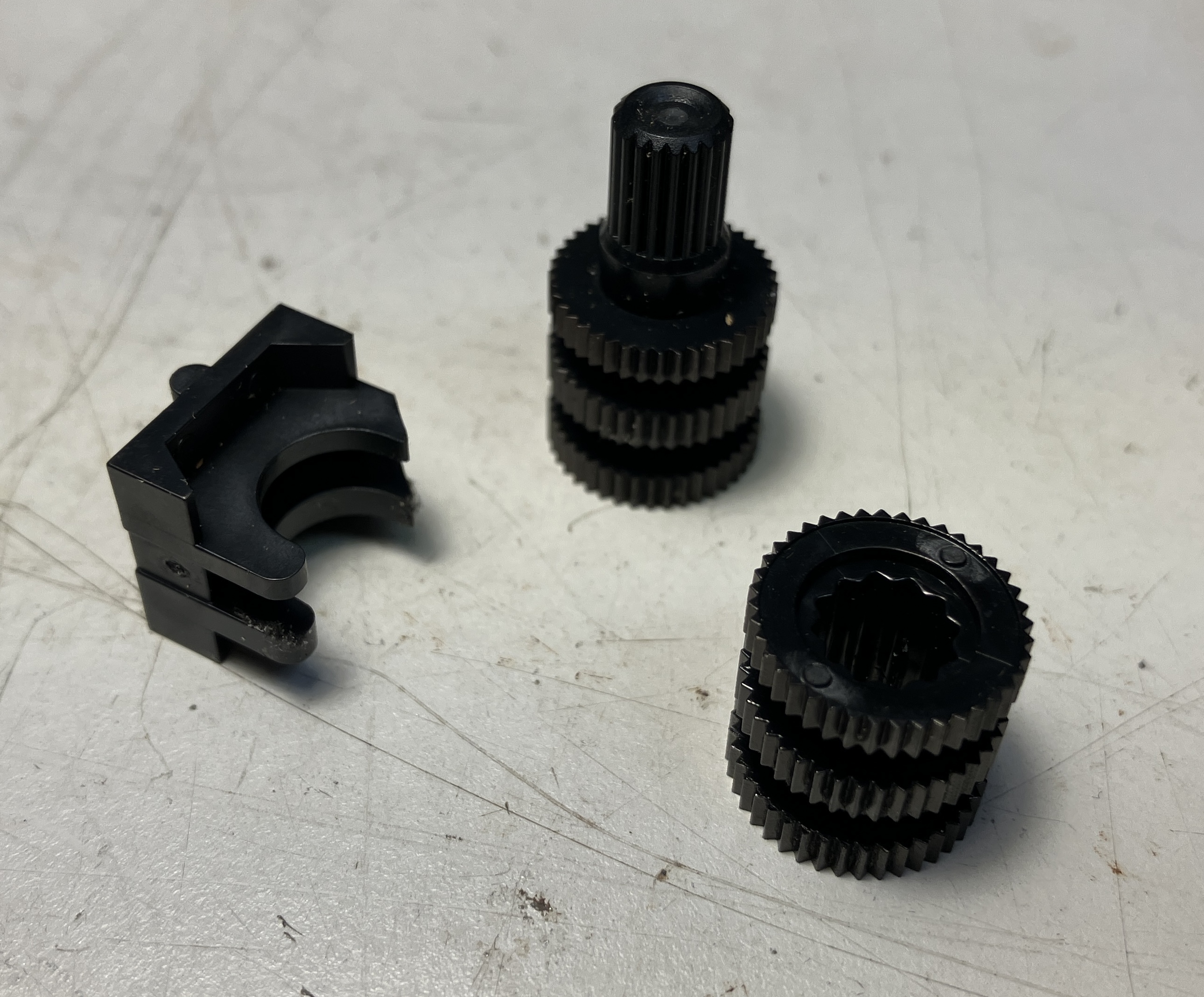
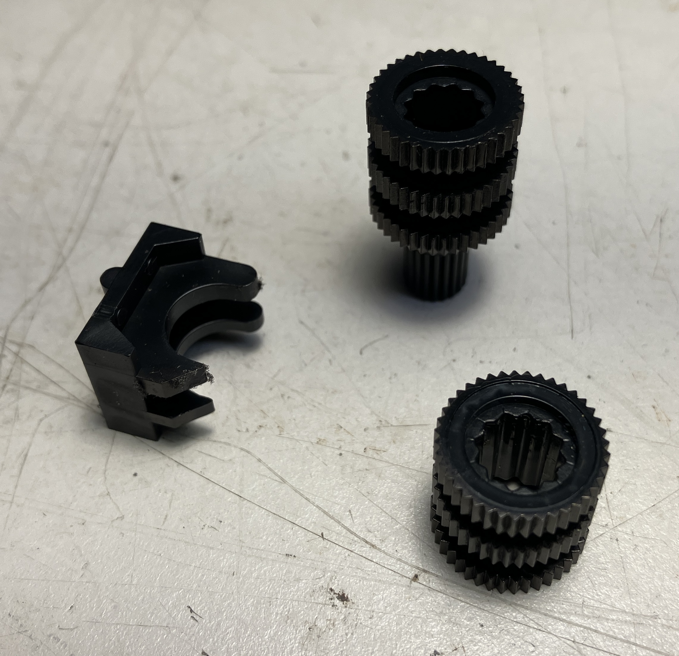
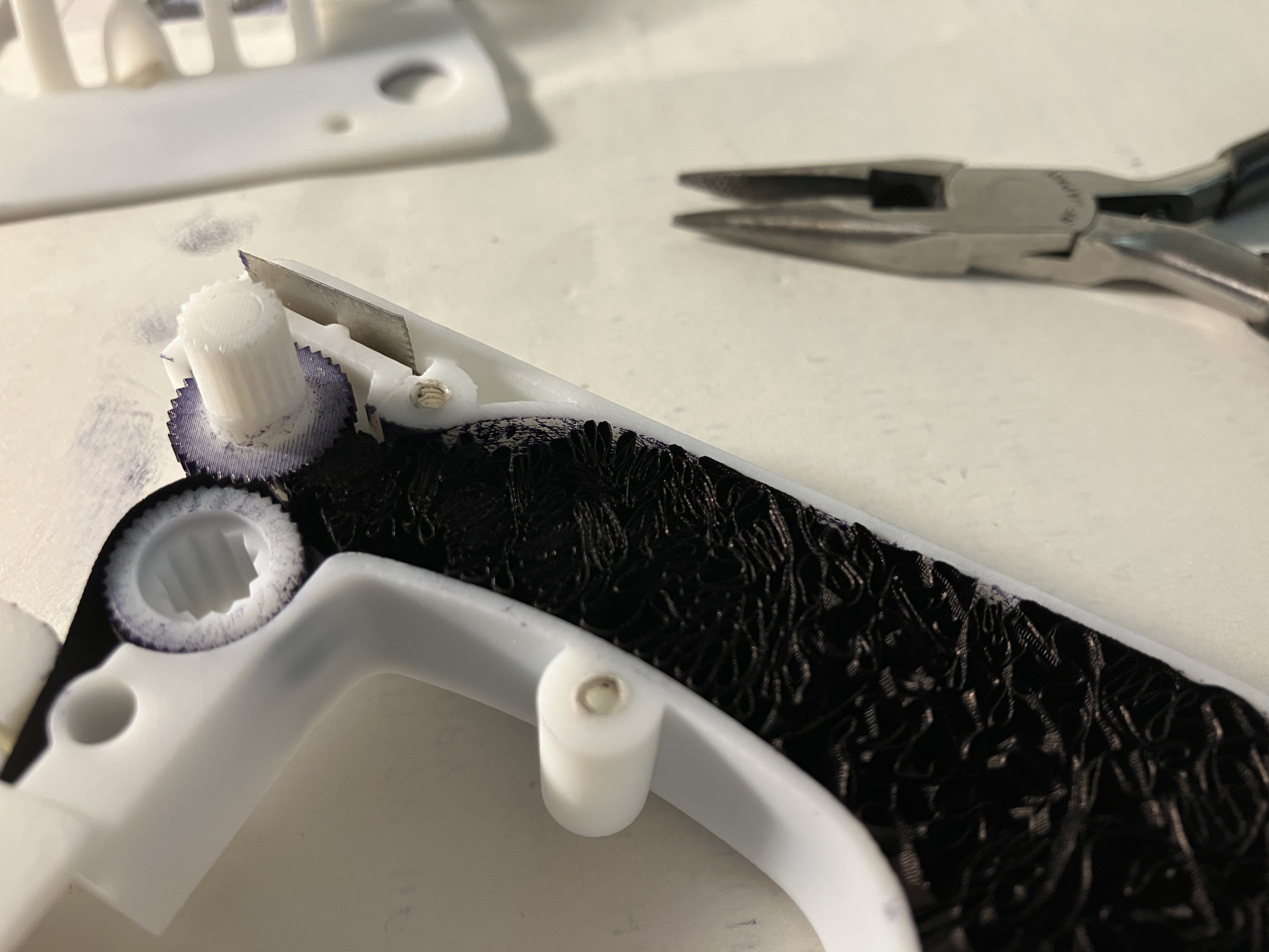
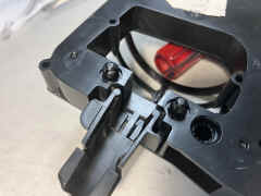
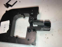
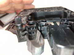
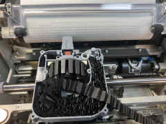
ribbon advance gear is held against idler by small metal
spring piece
 |
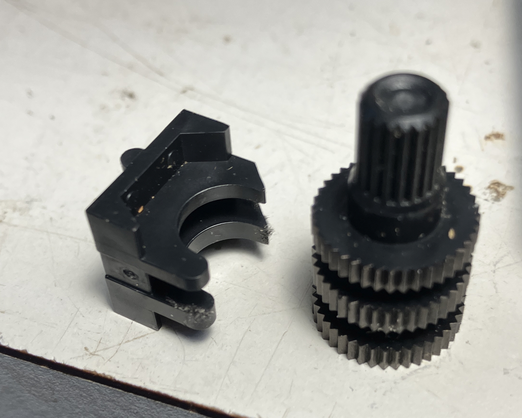
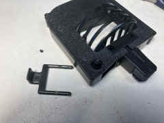
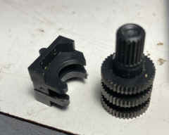
advance gear assembly slides out
 |
idler is held in place by tension from advance gear
 |
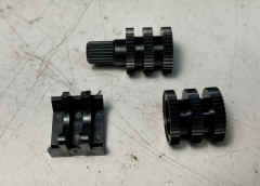
| Gear photos 7/28/25 |
 |
 |
 |
== |
 |
 |
 |
== |
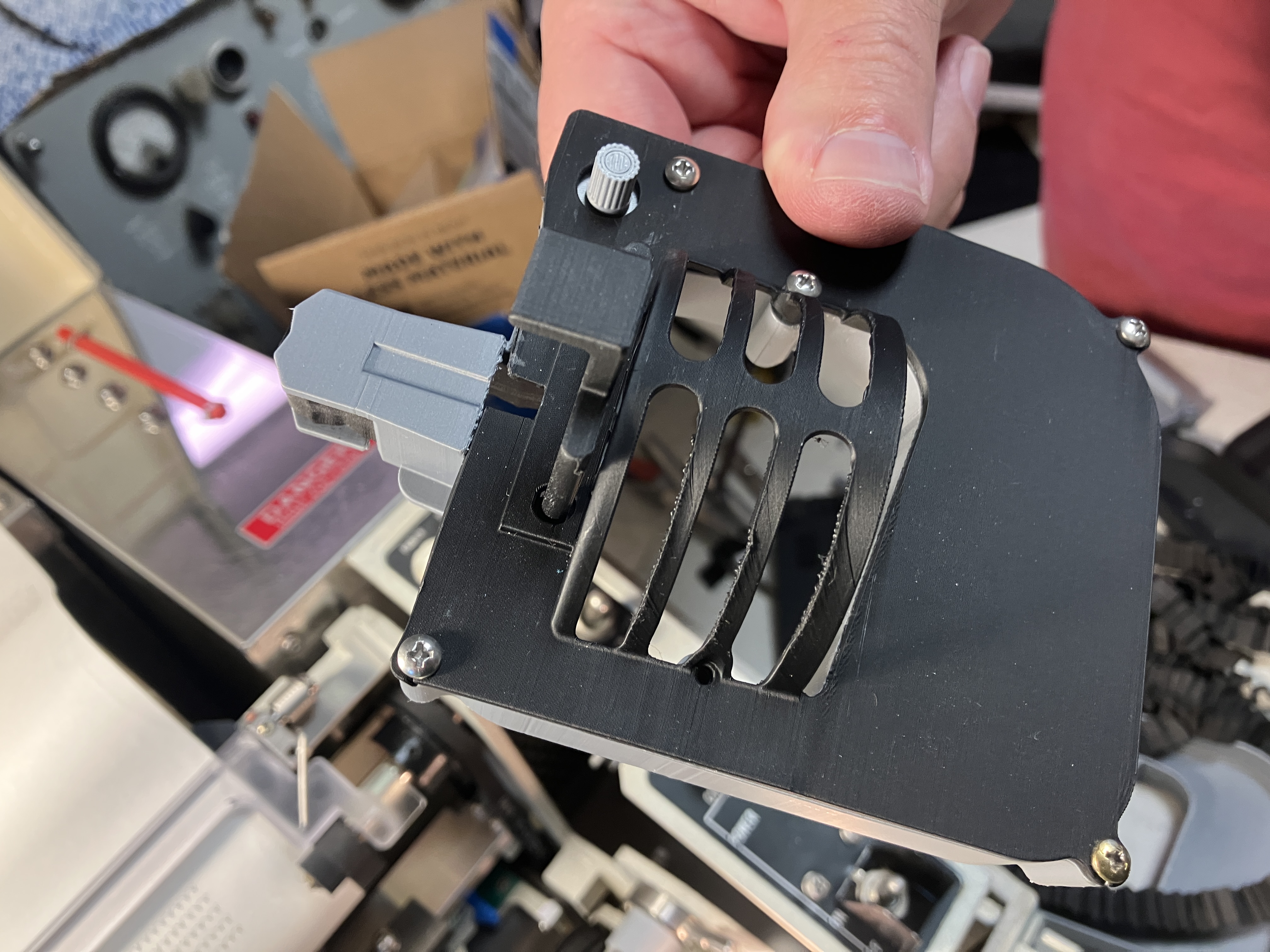
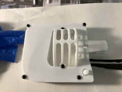
top
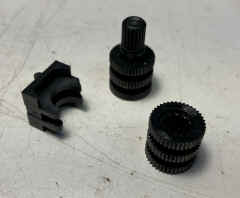 |
bottom
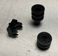 |
side
 |
== |
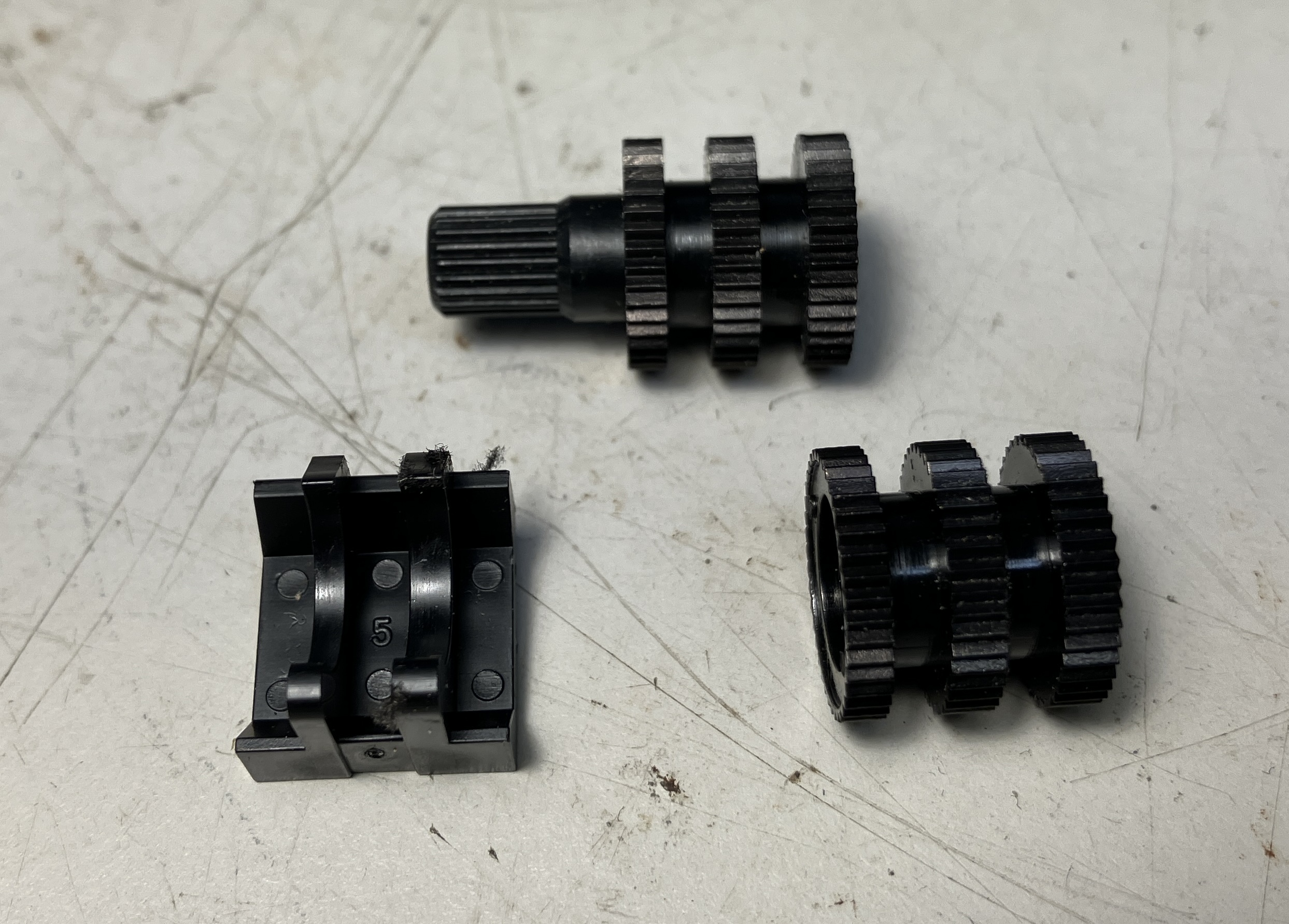
Drive shaft
 |
 |
== |
== |
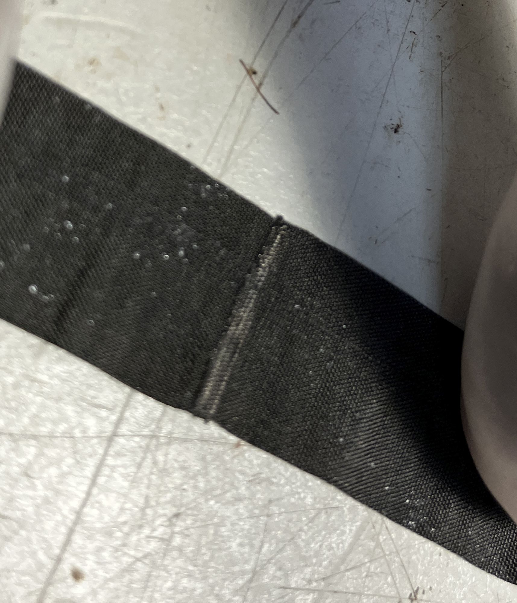
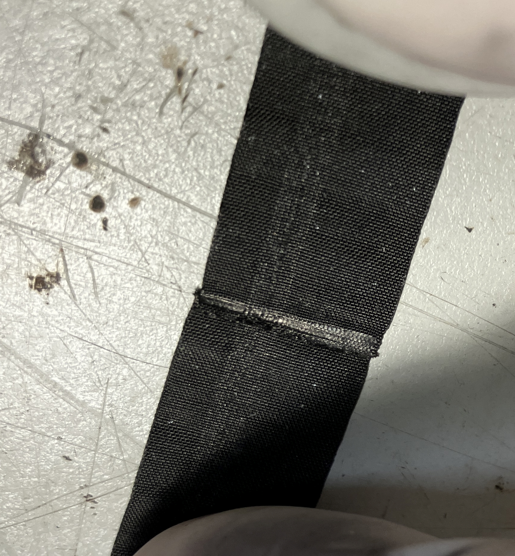
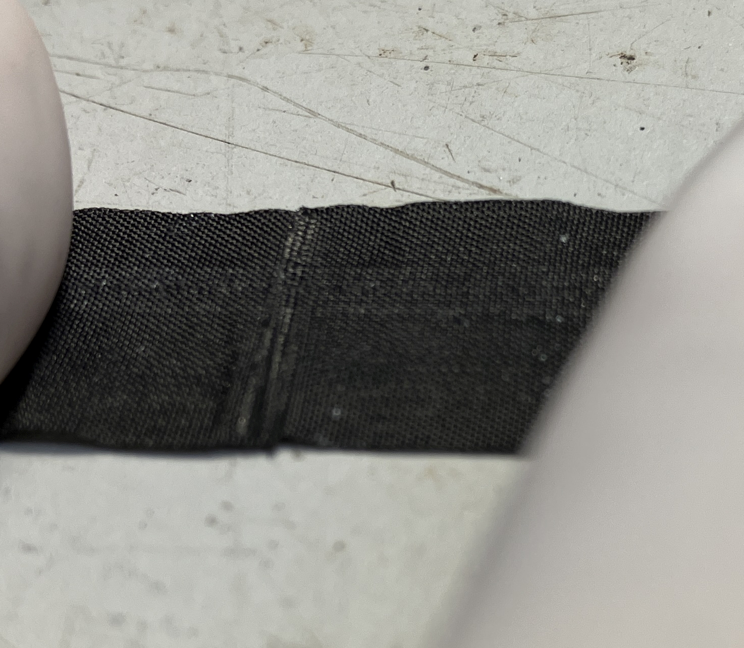
| Ribbon must be spliced to
make a loop |
 |
 |
 |
== |
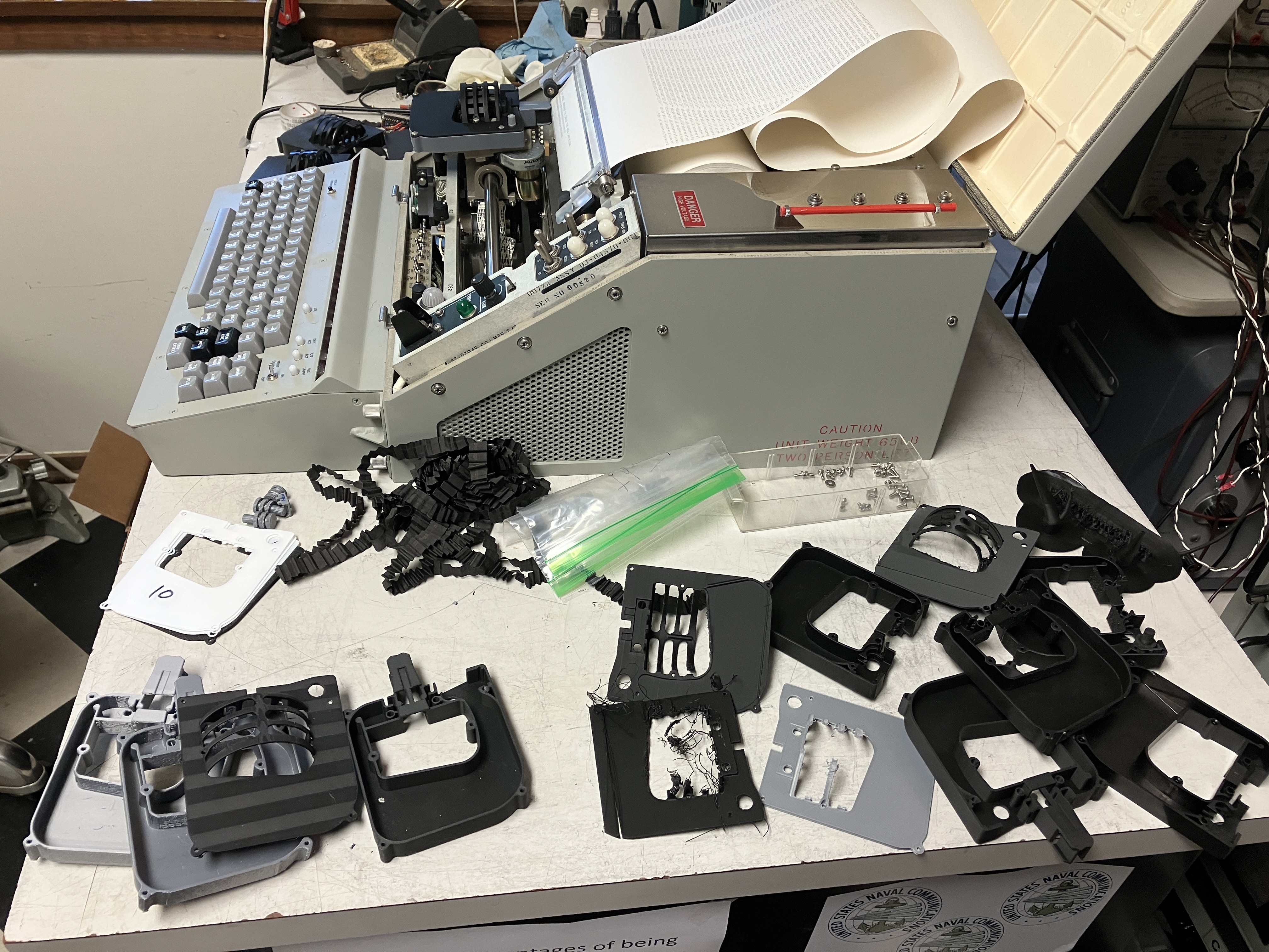
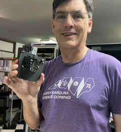
Successful 3D printed version test 8/9/25 - all
thanks to modeler/printer John Toebes
|
First test
 |
Top on
 |
Success!
 |
== |
It took several iterations
 |
Happy John
 |
|
== |
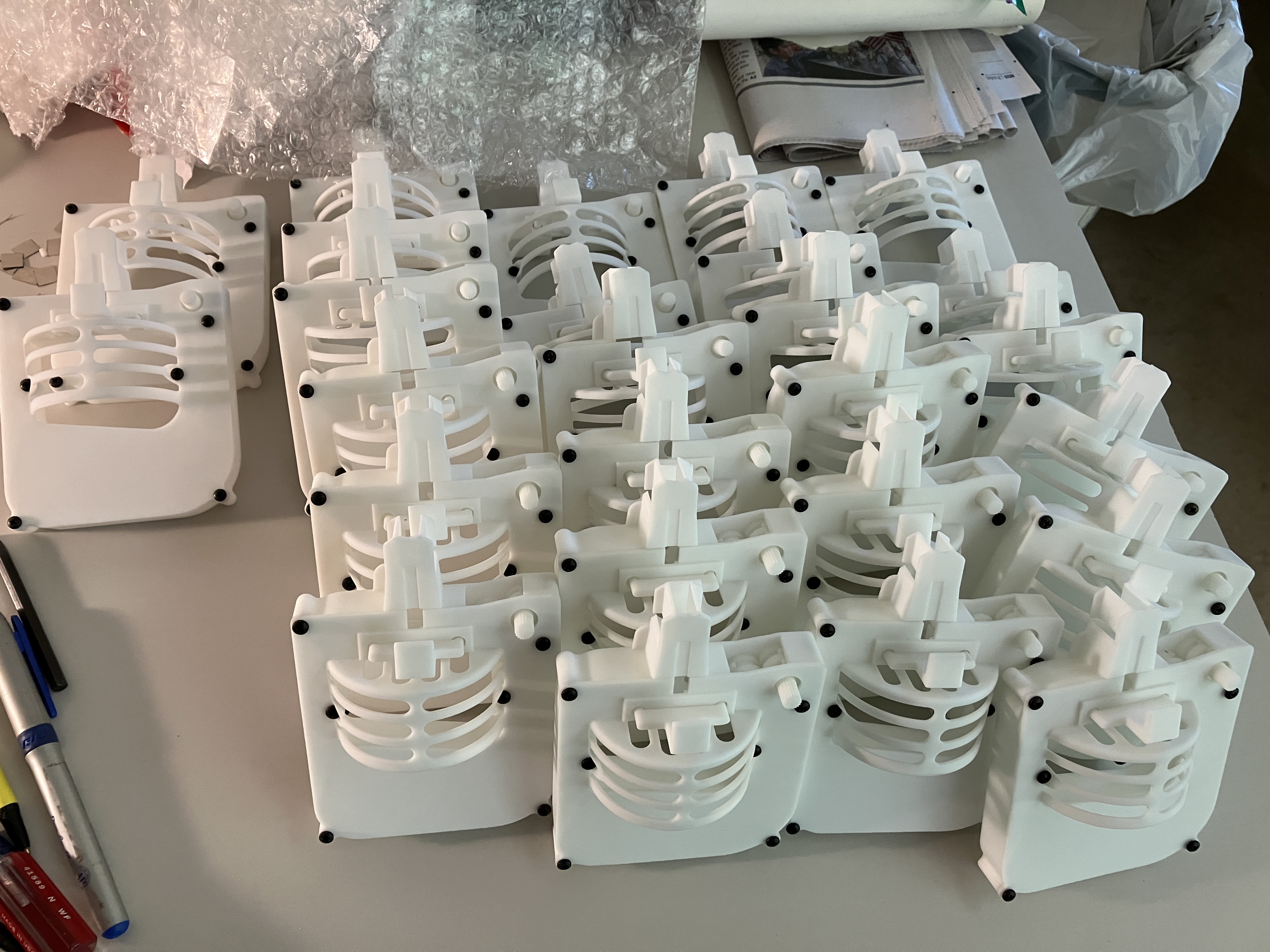
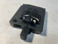
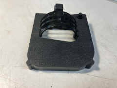
SLS production prototype - test 8/15/25
|
 |
Ribbon loop from an old busted cartridge
 |
Old ribbon but good enough for testing

|
==== |
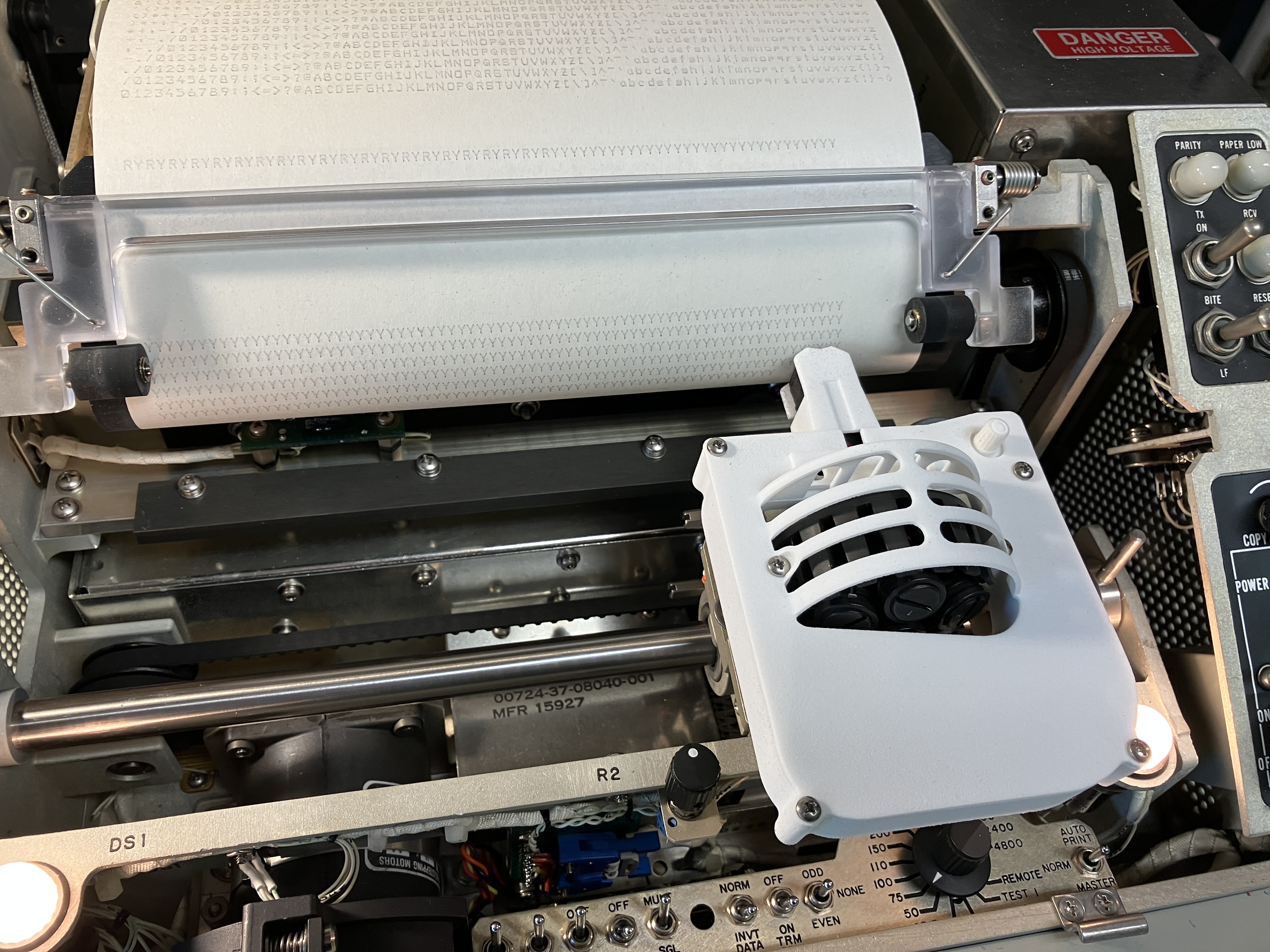
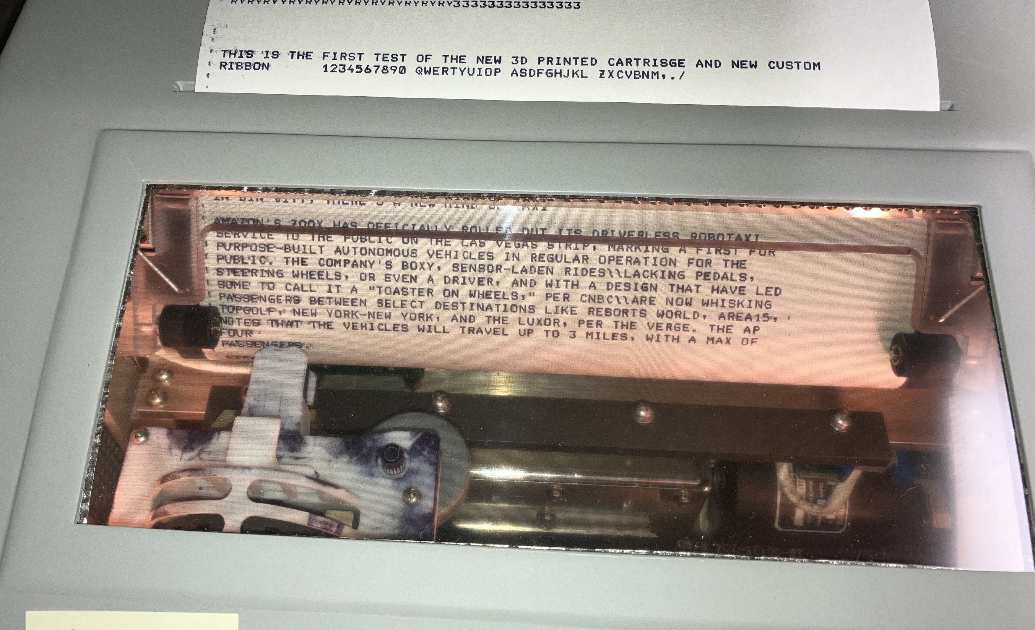
First test of production version with custom ribbon
|
 |
Before shipping
 |
In case you want to print your own
See HERE
|
== |
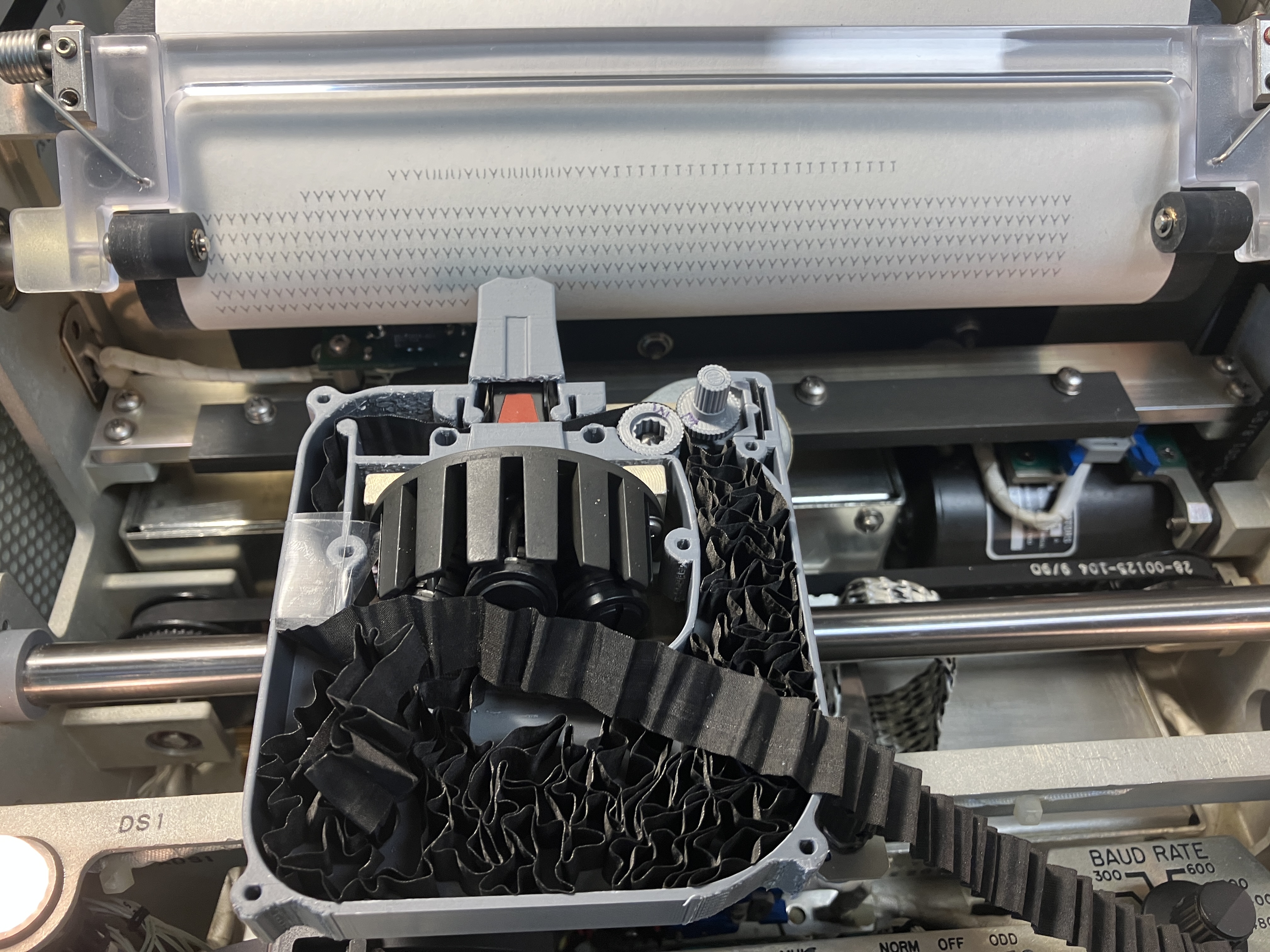
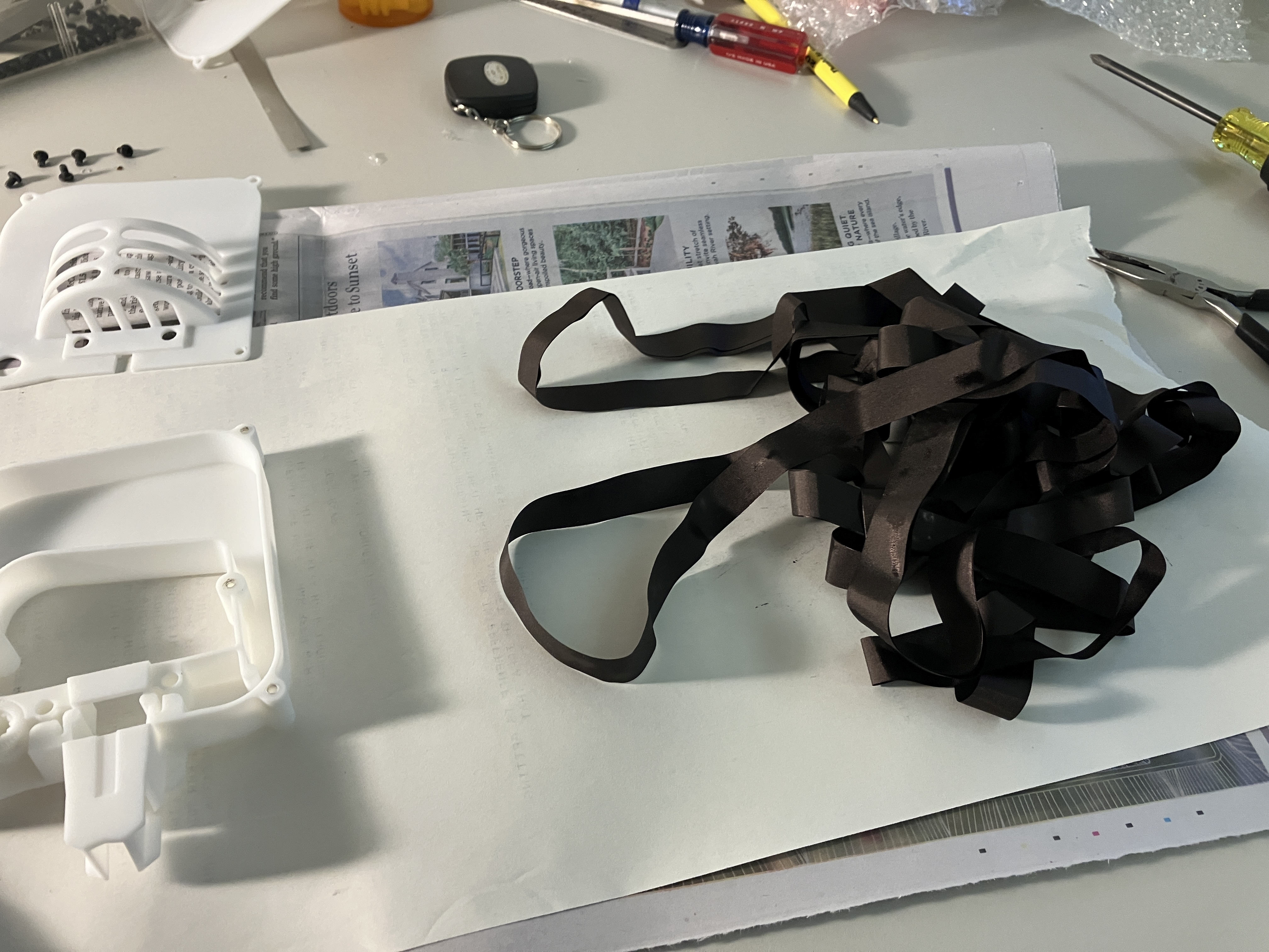
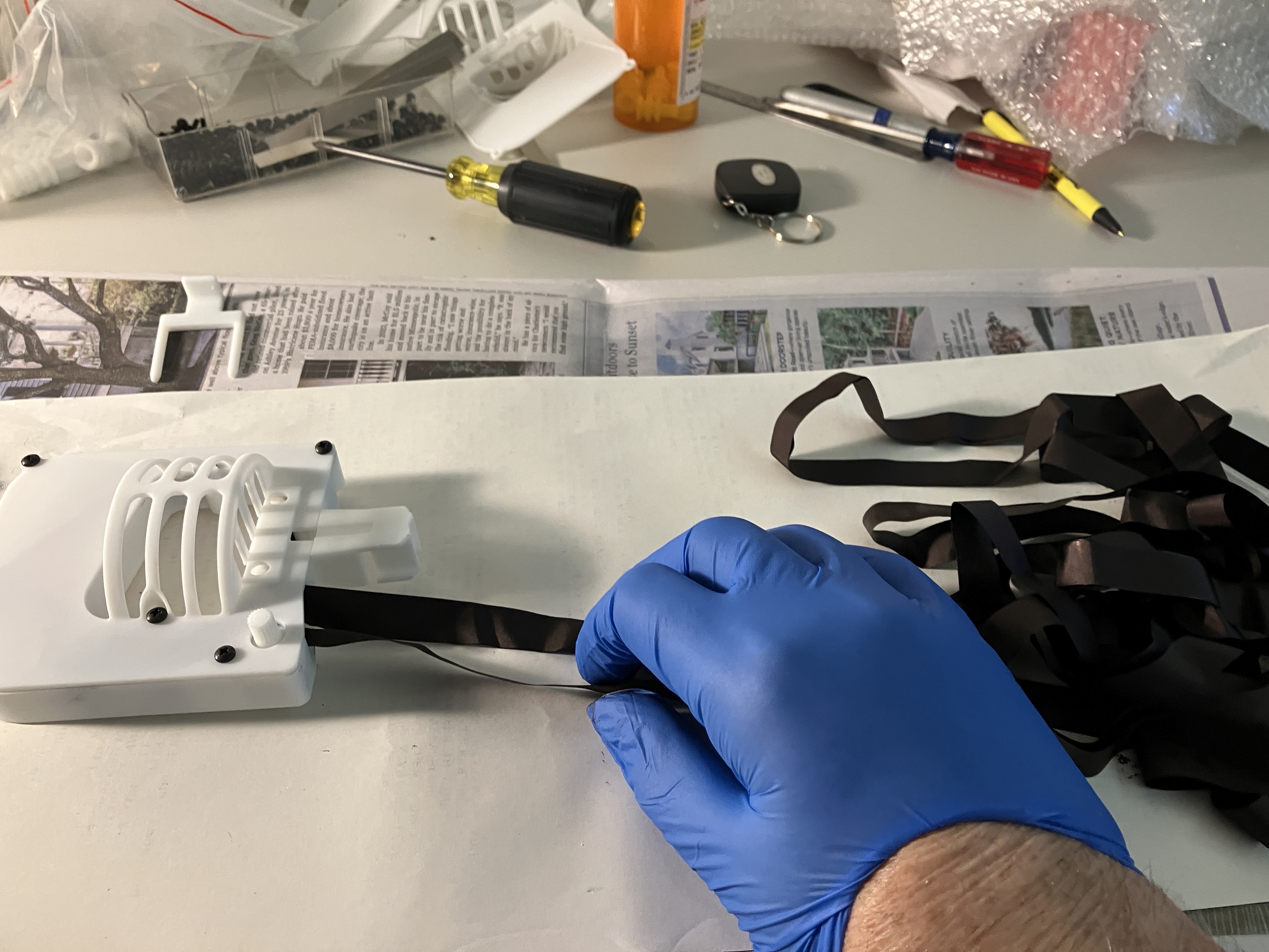
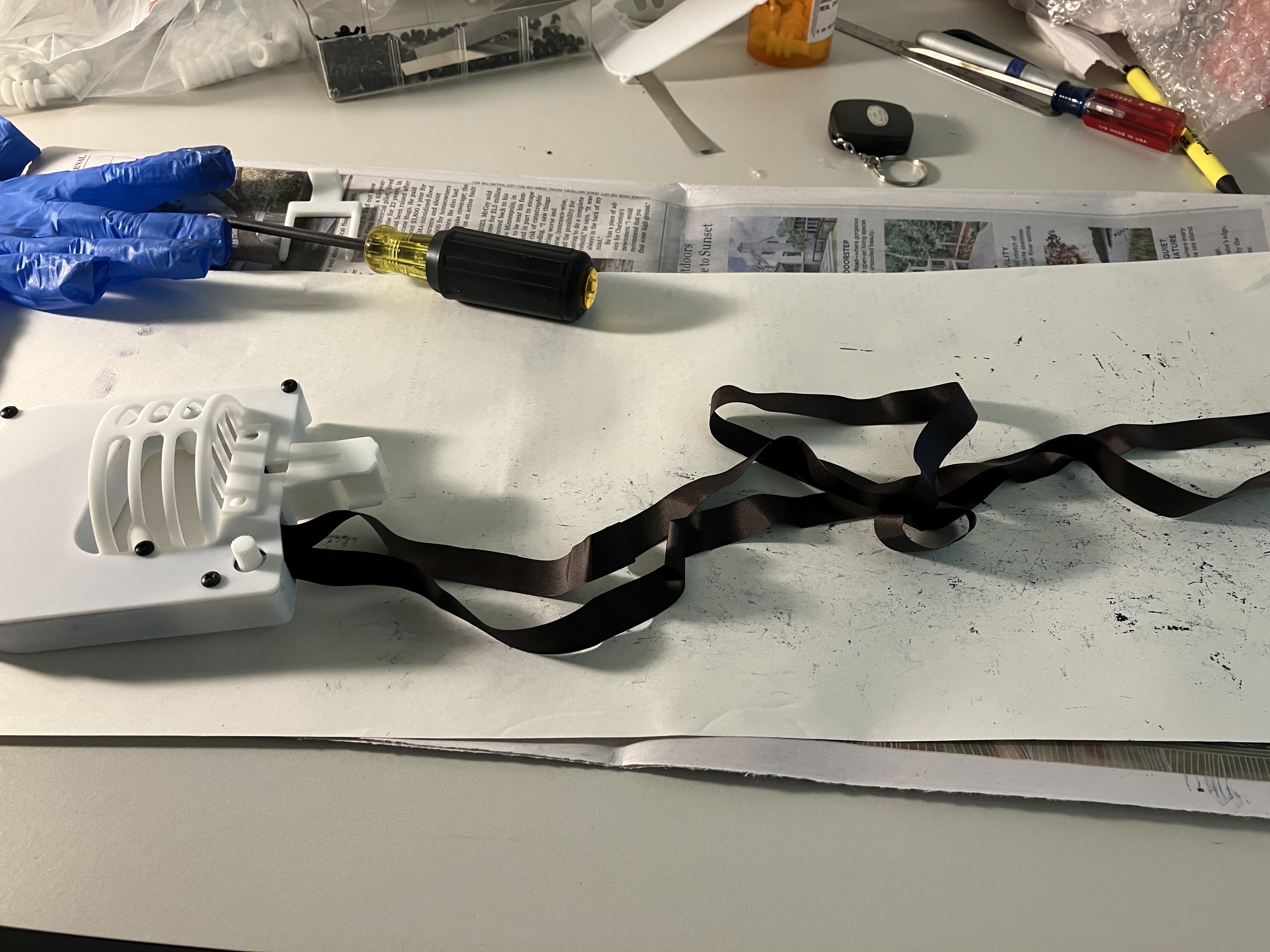
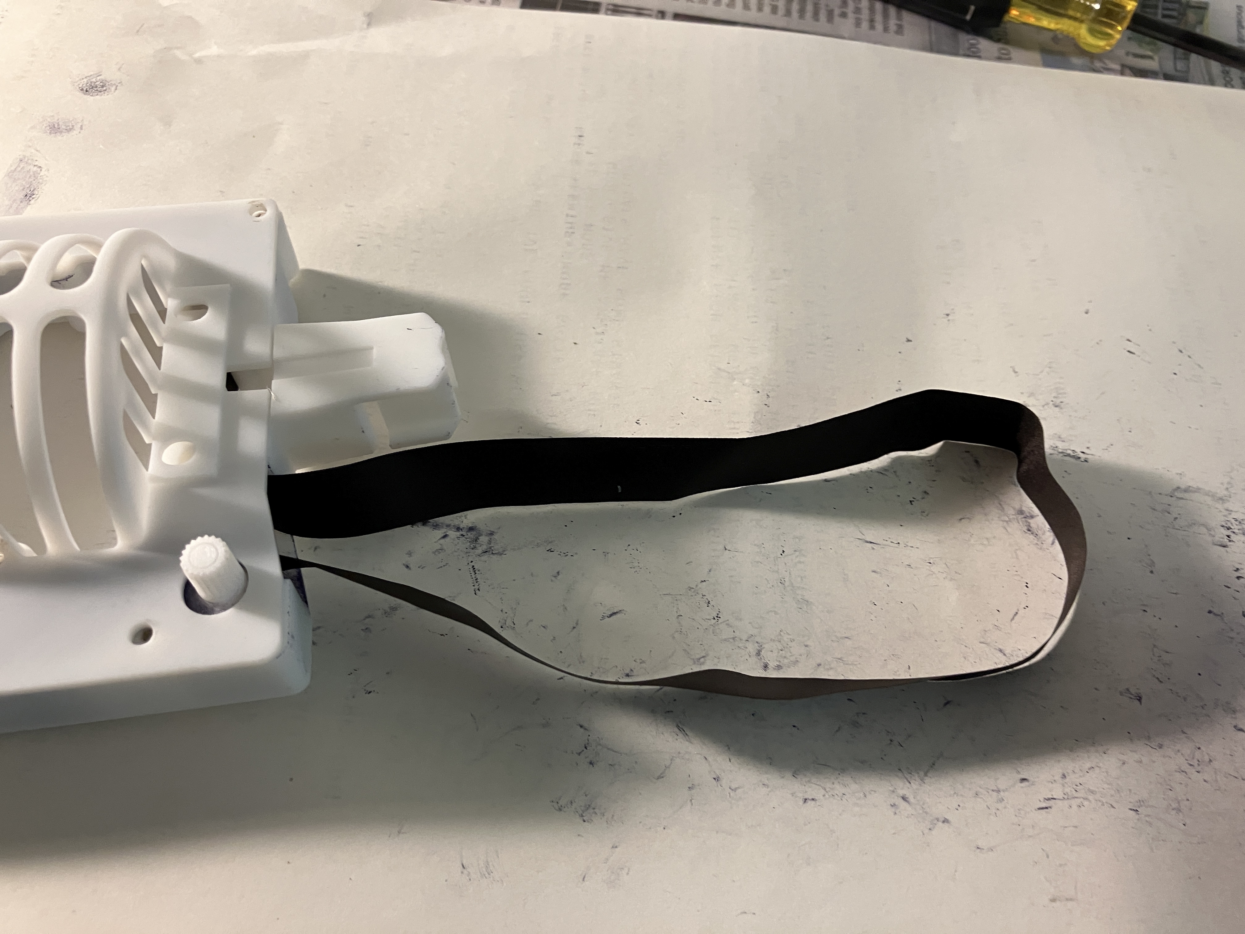
INSTALLING THE RIBBON
|
| Ready to begin - try to keep the ribbon loose as
you take it out of the package - avoid knots! |
 |
 |

|
== |
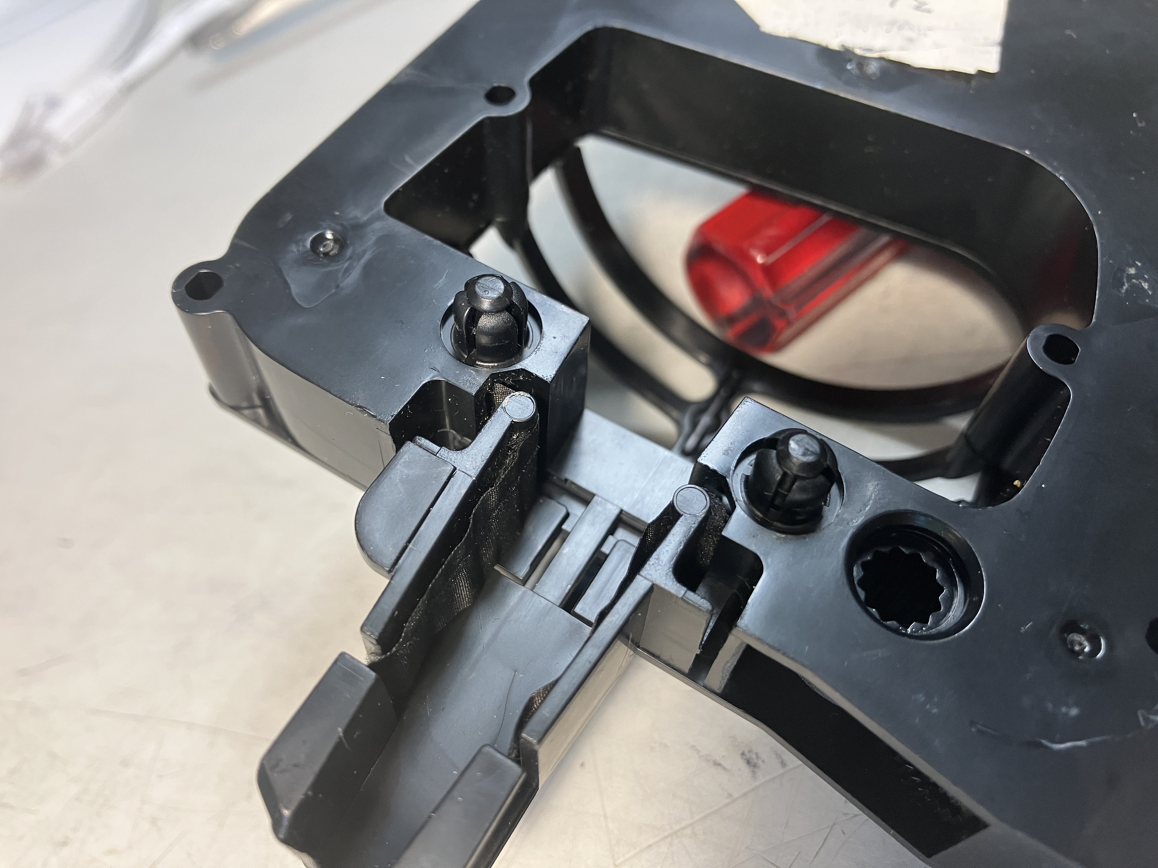
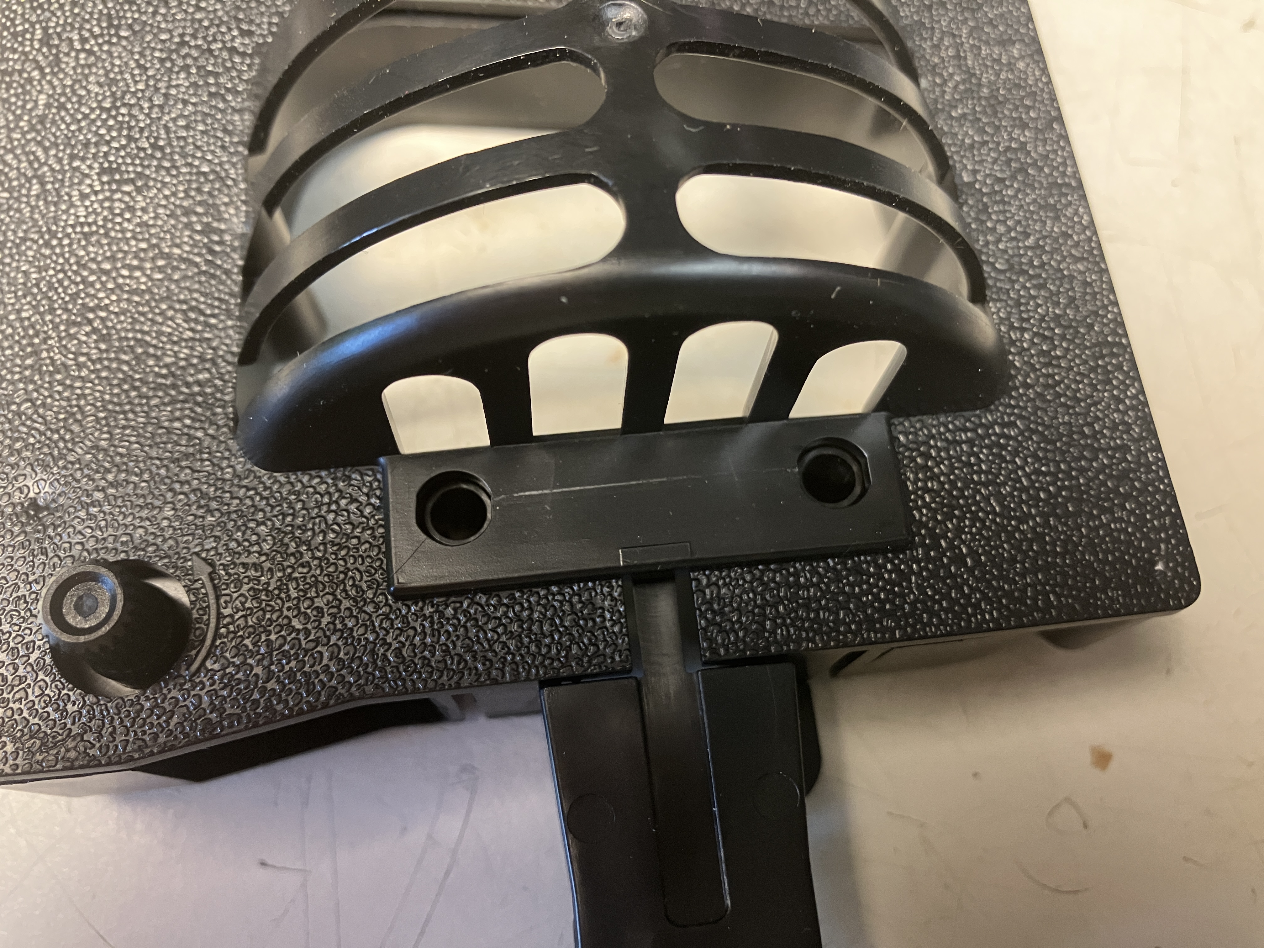
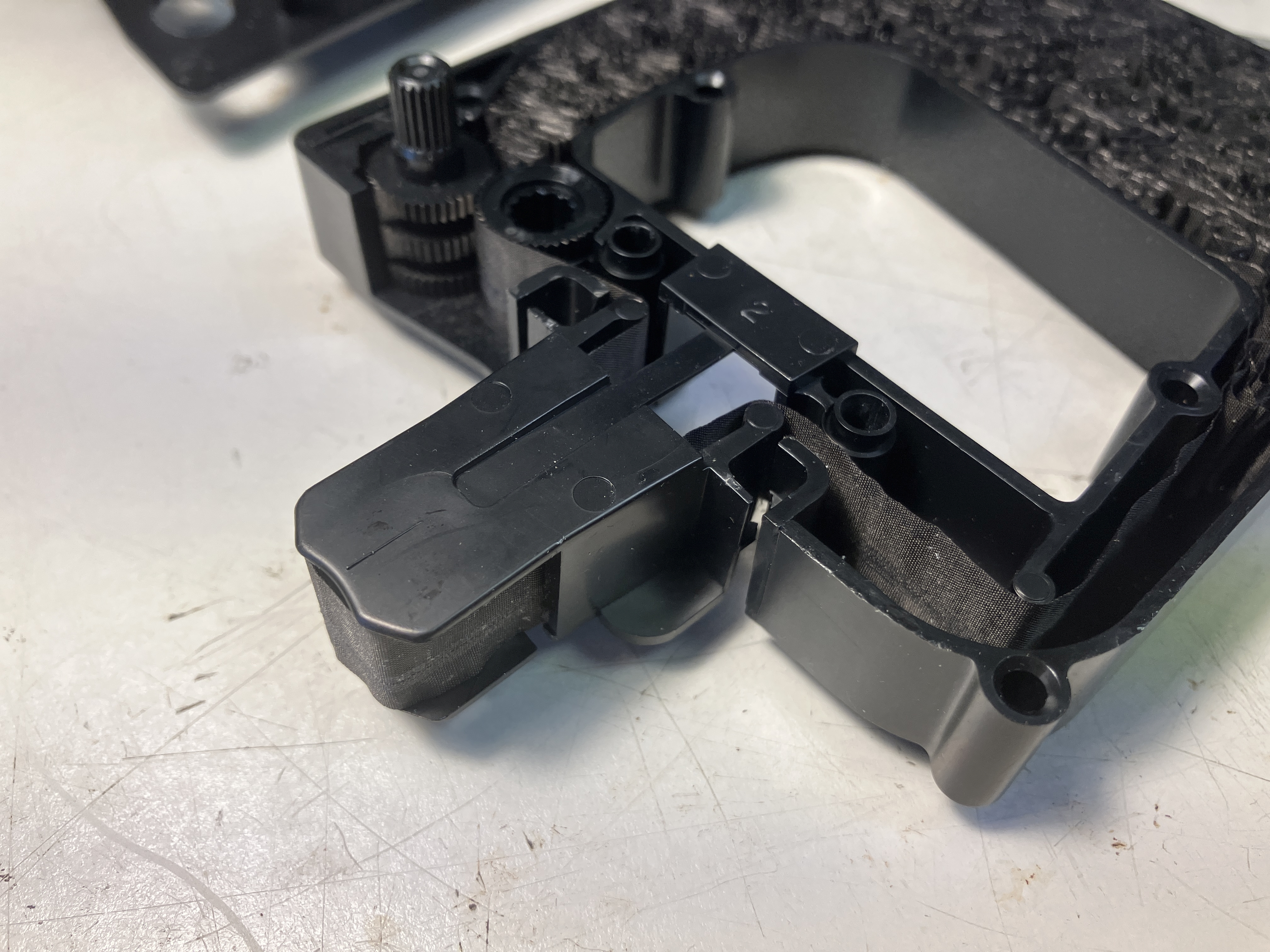
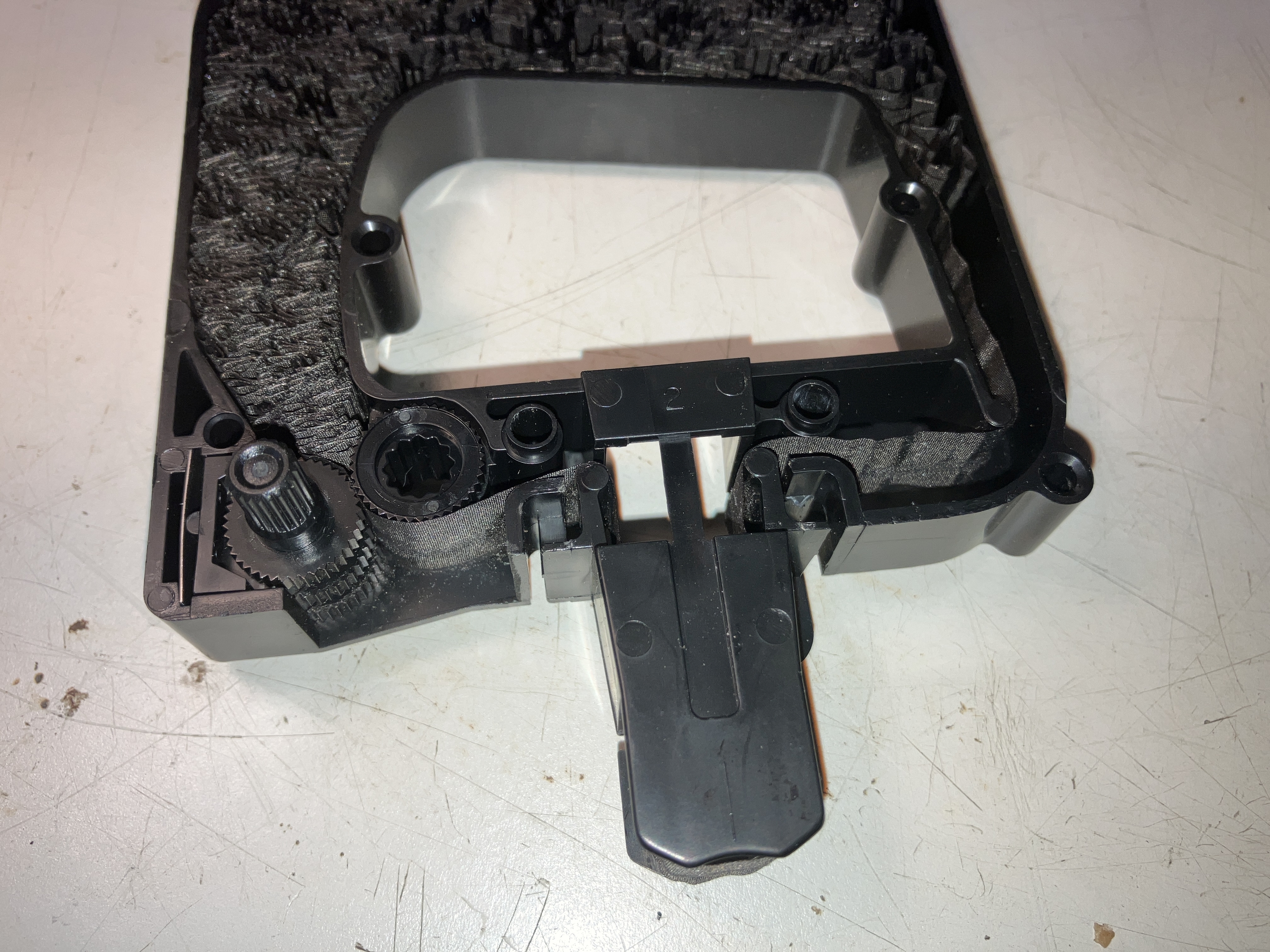
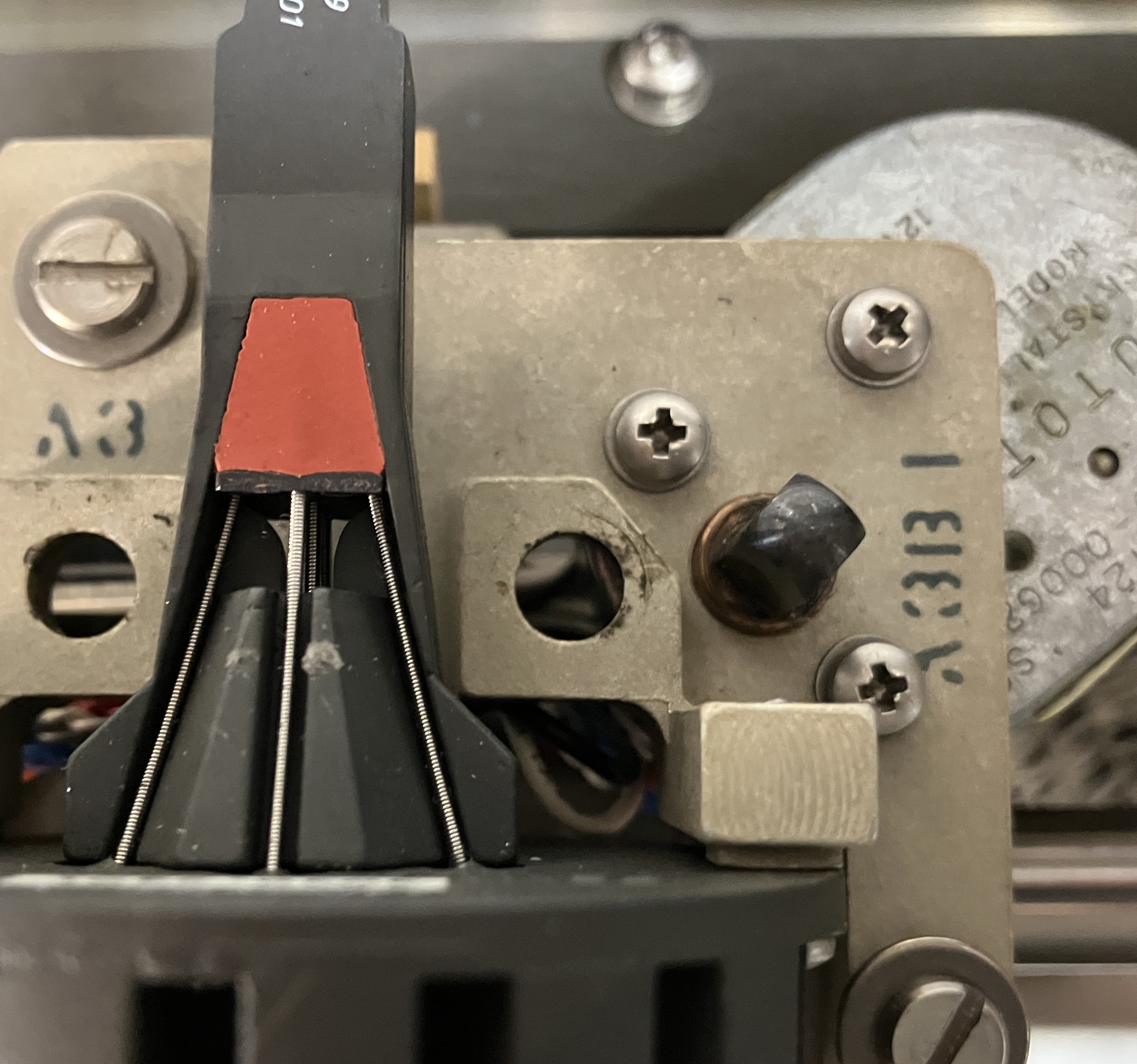
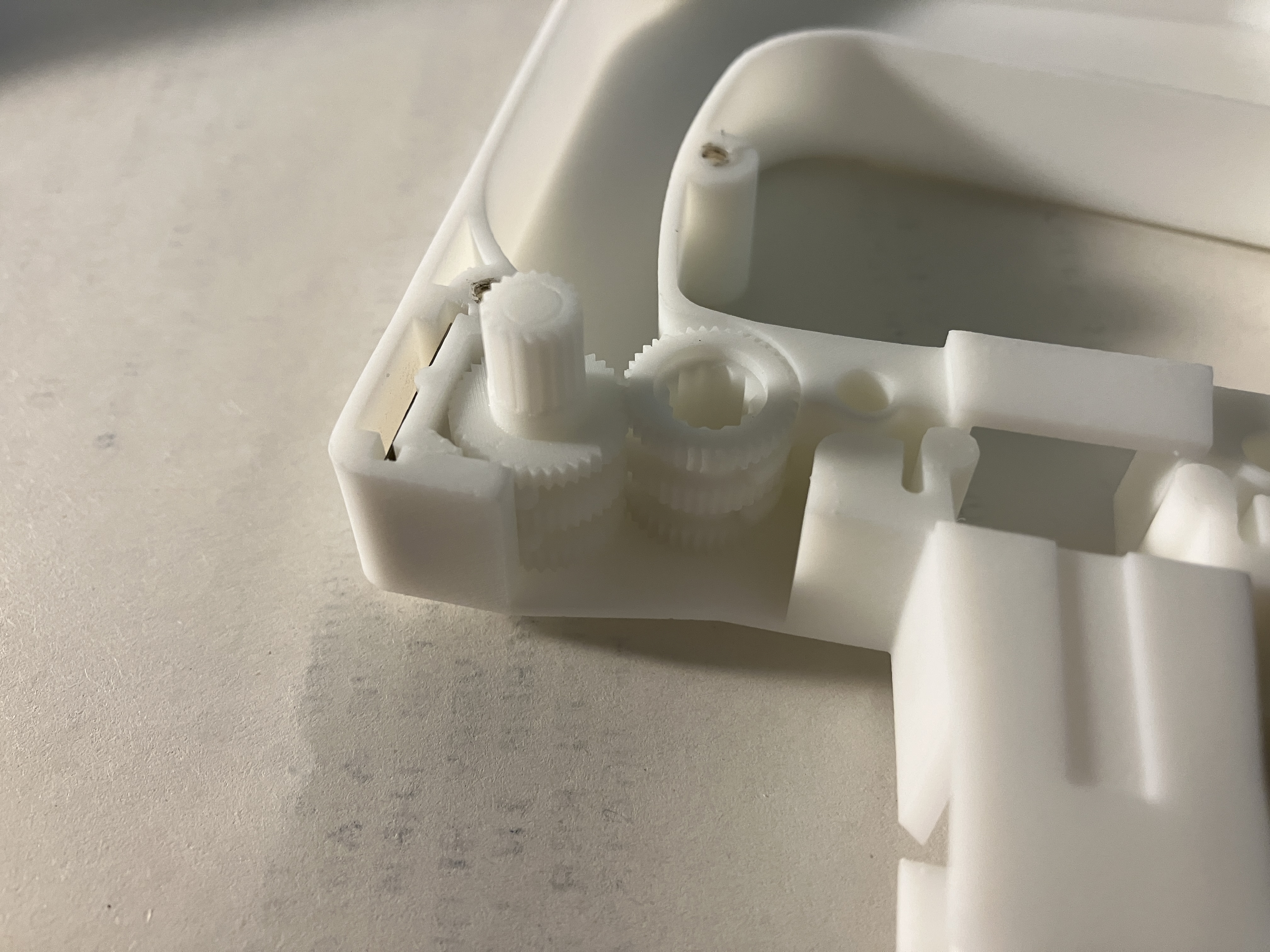
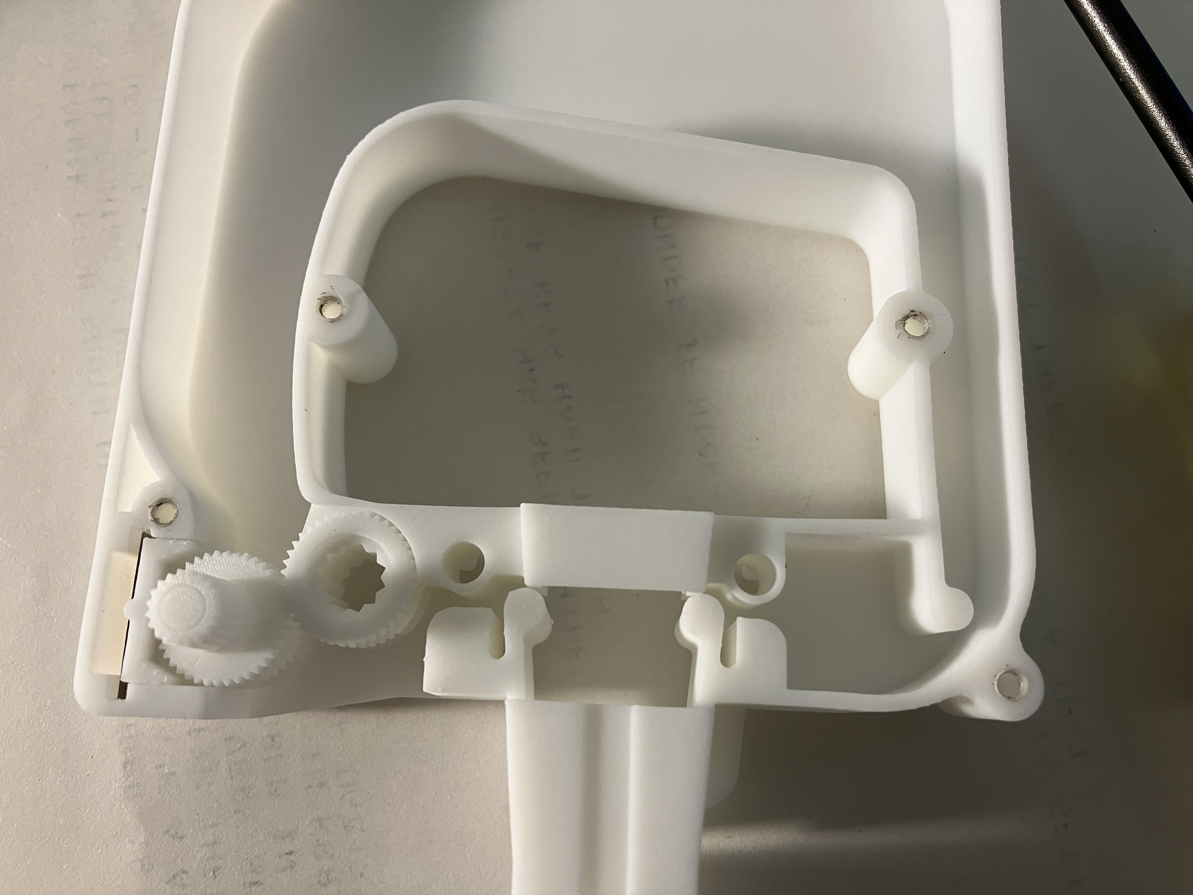
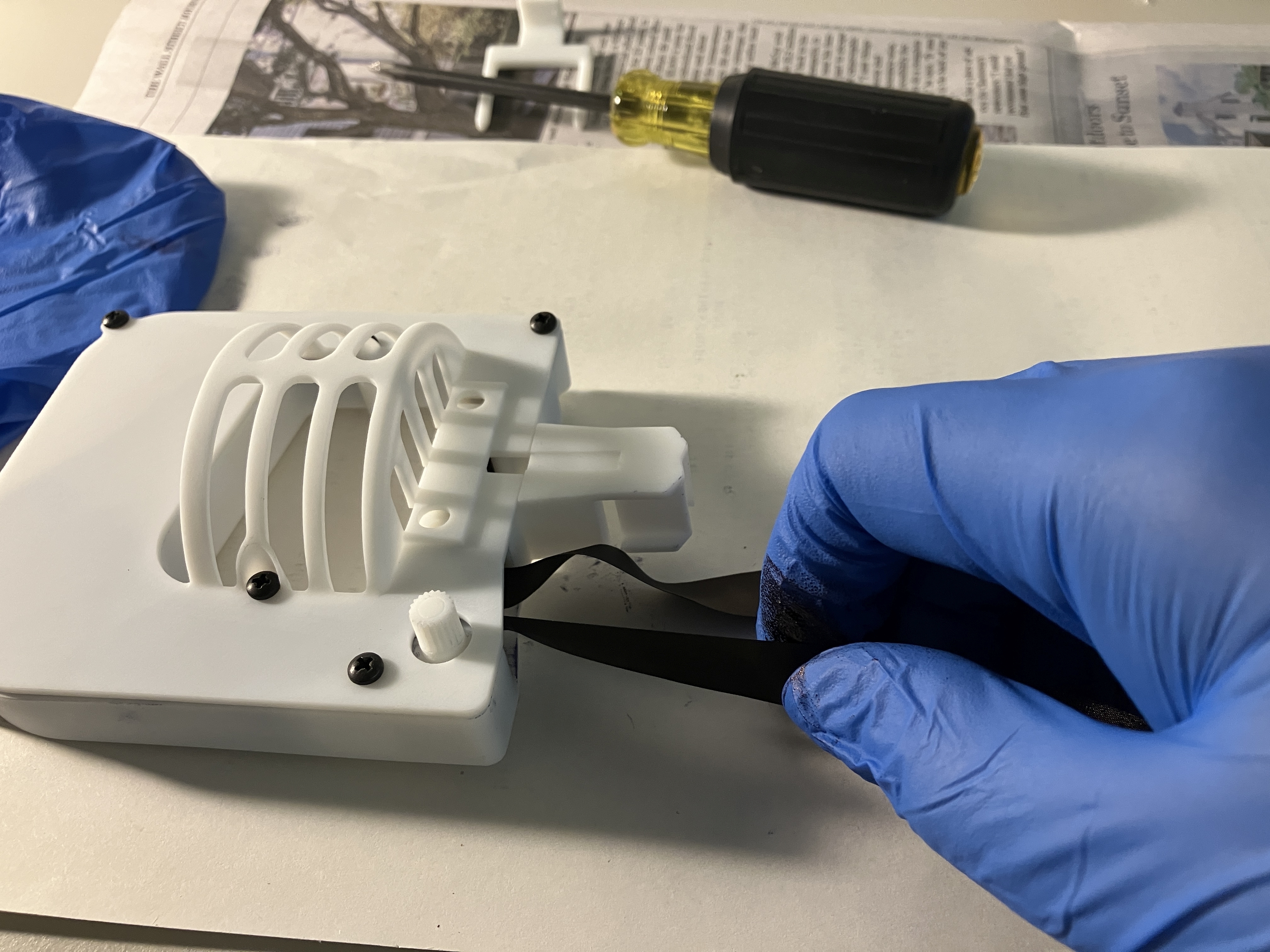
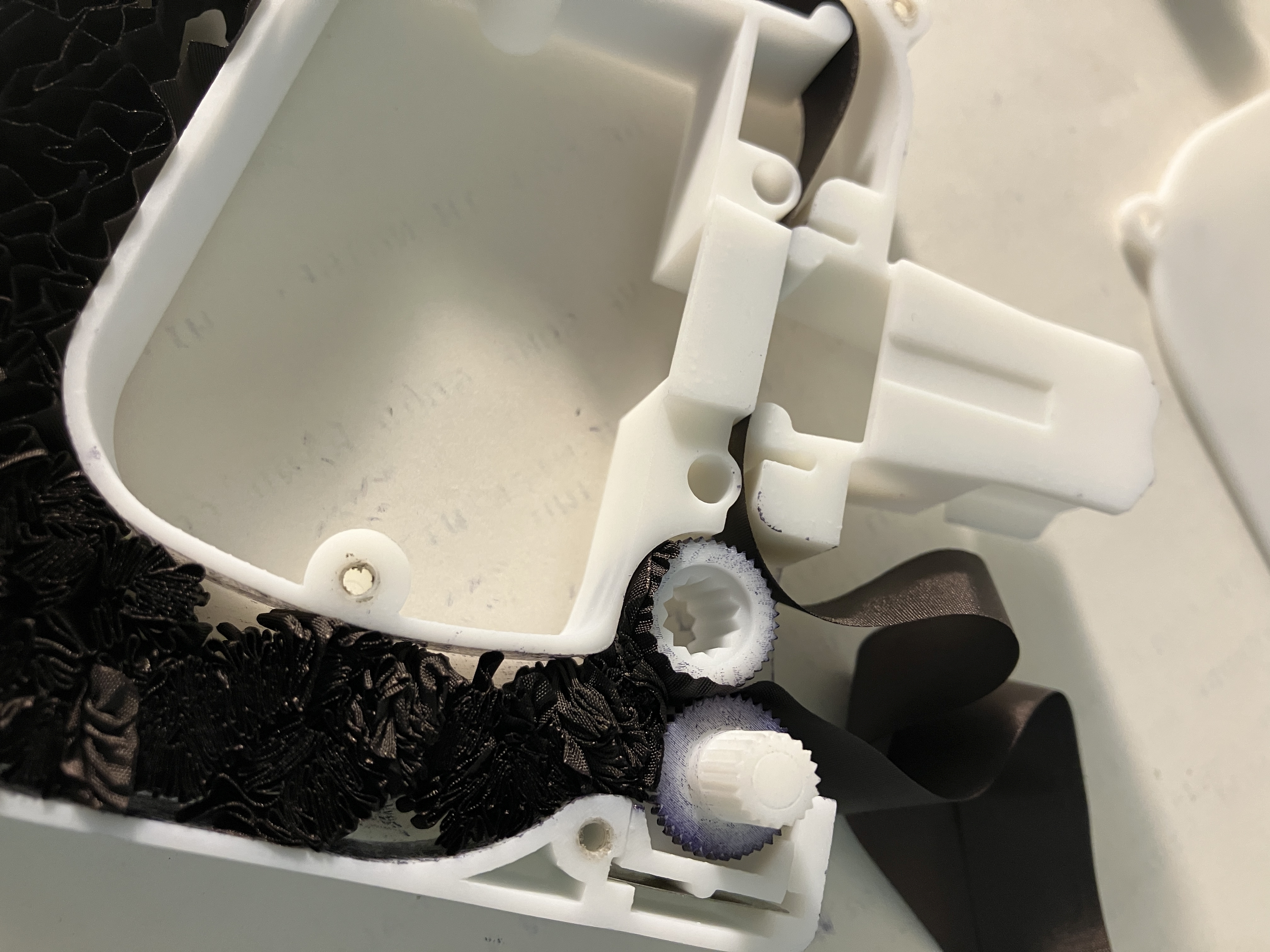
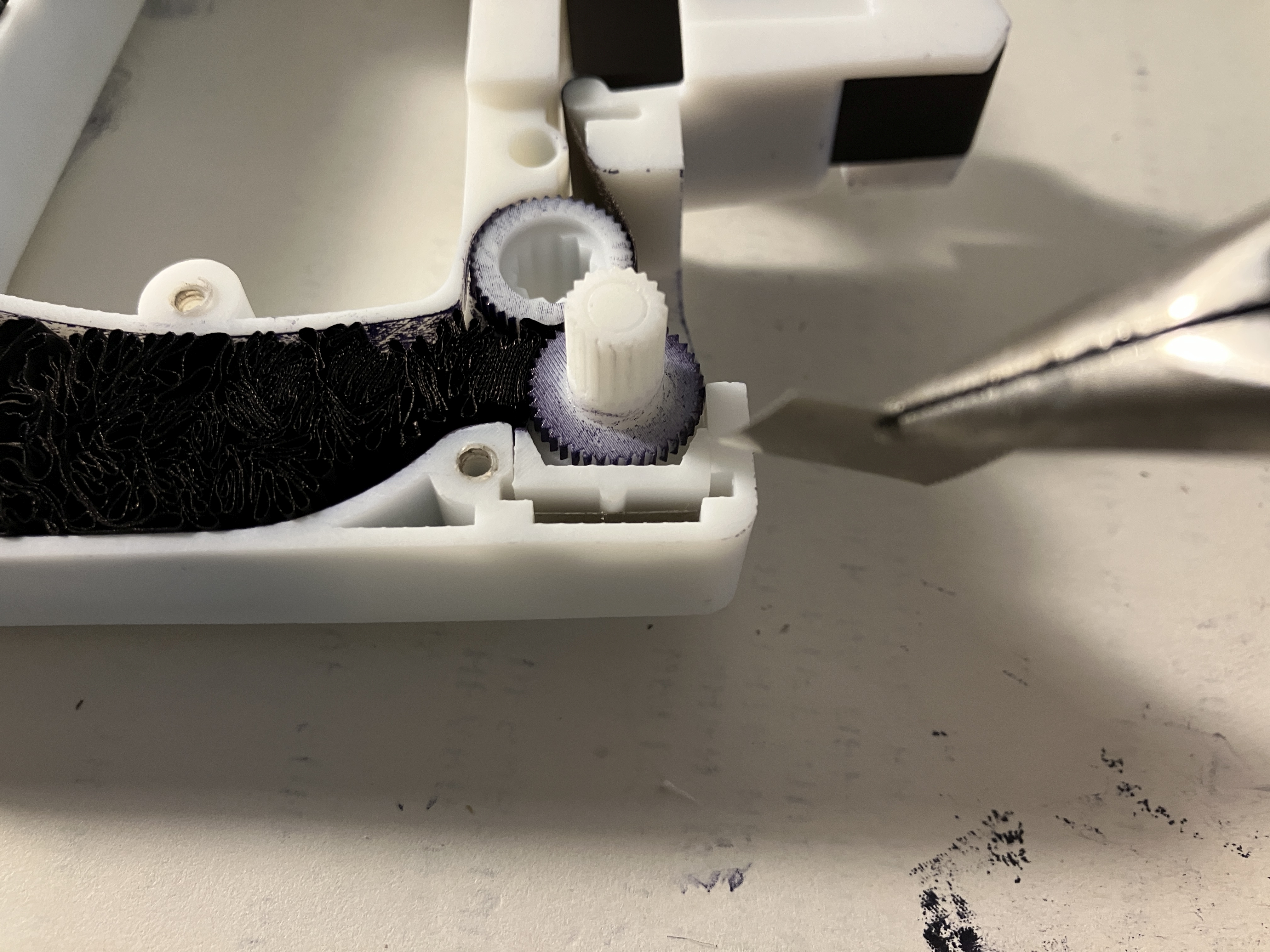
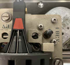
| Close up of drive gear and manual gear - note
that there is a flat piece of spring steel that applies tension to the
sliding bracket that cradles the manual gear |
 |
 |
==
|
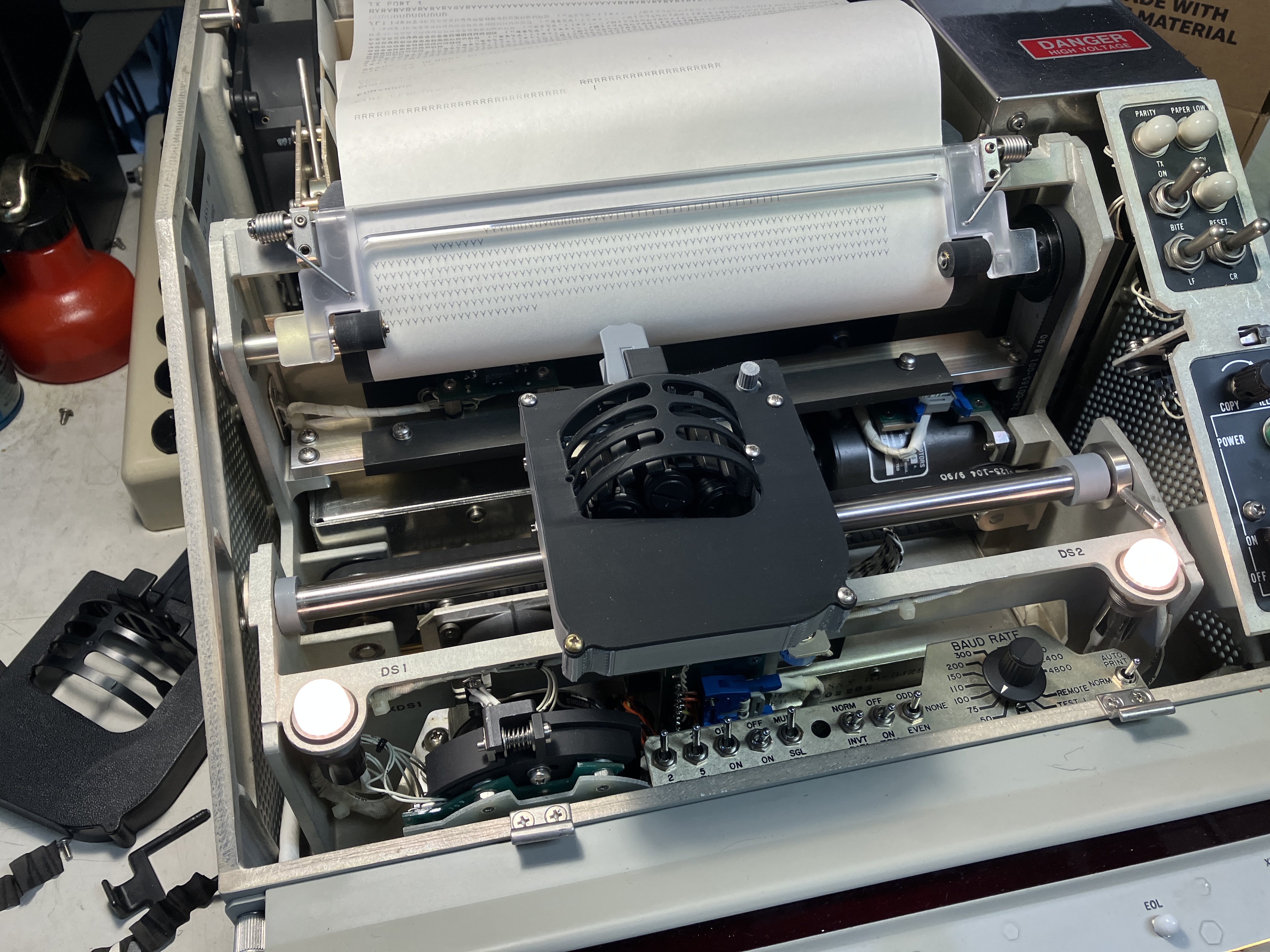
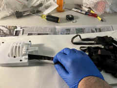
== |
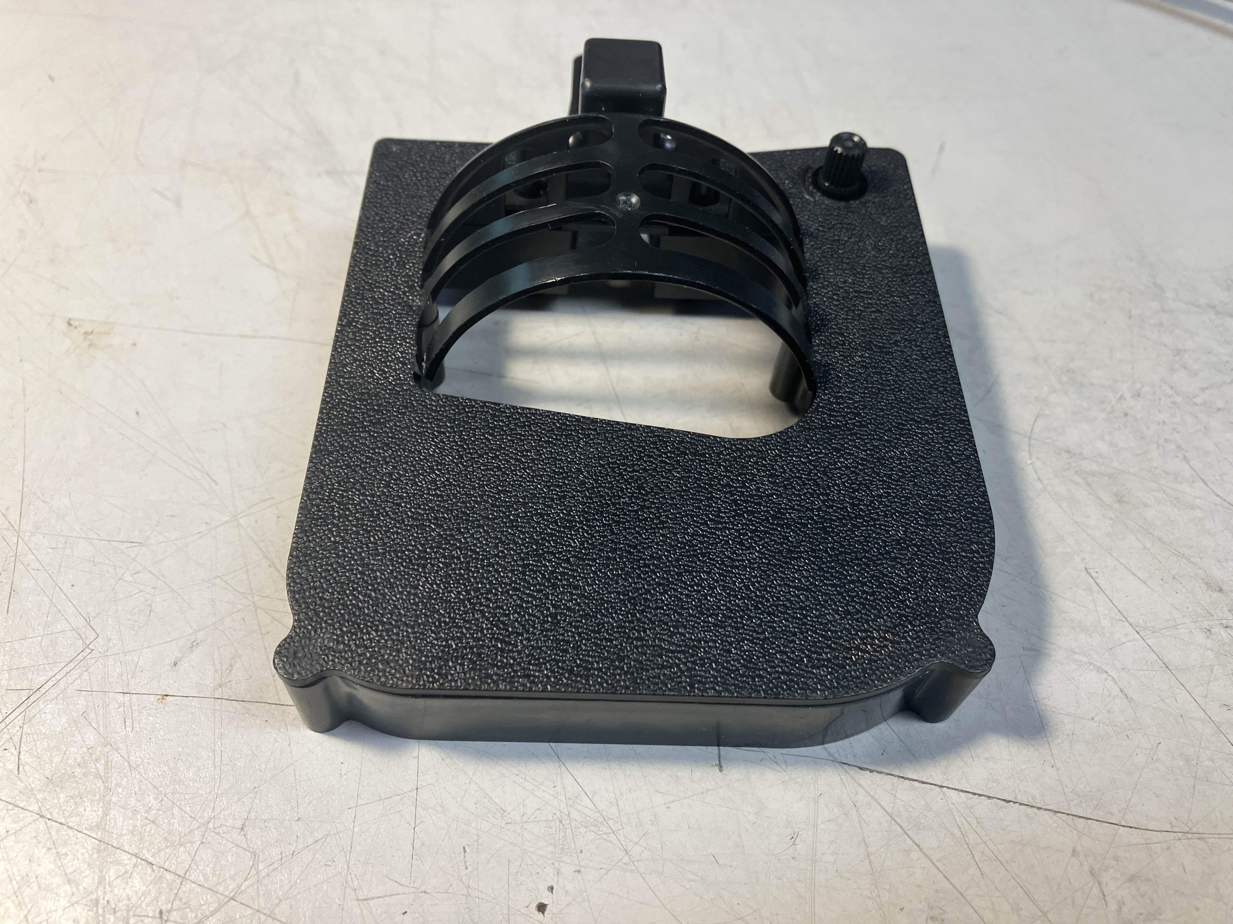
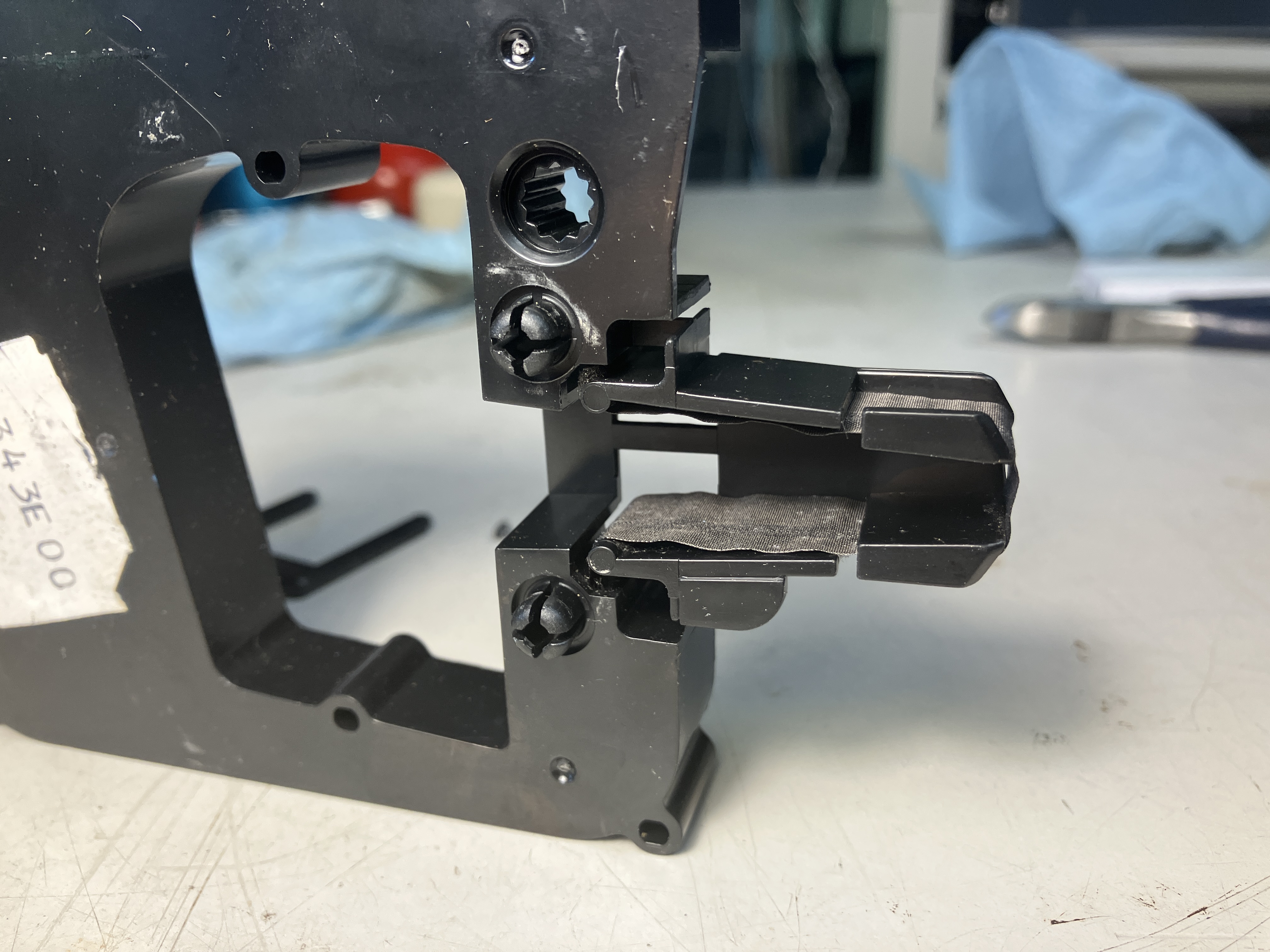
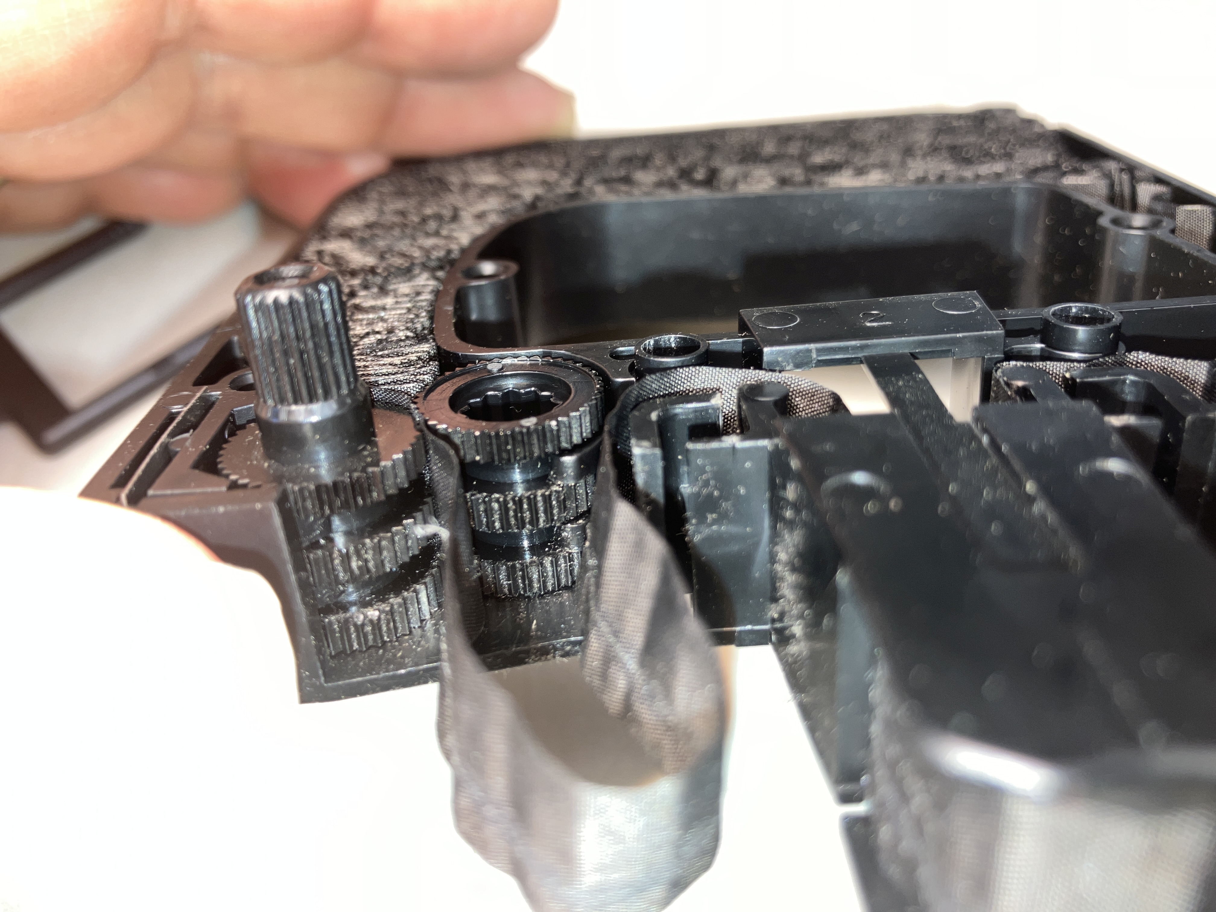
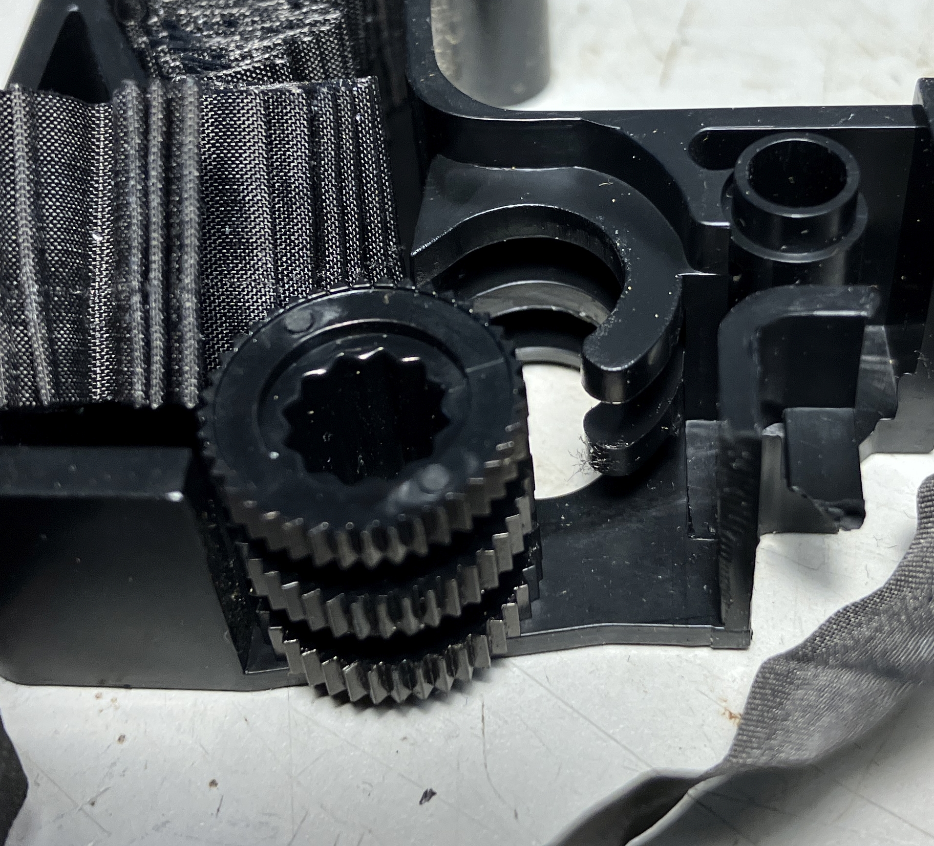
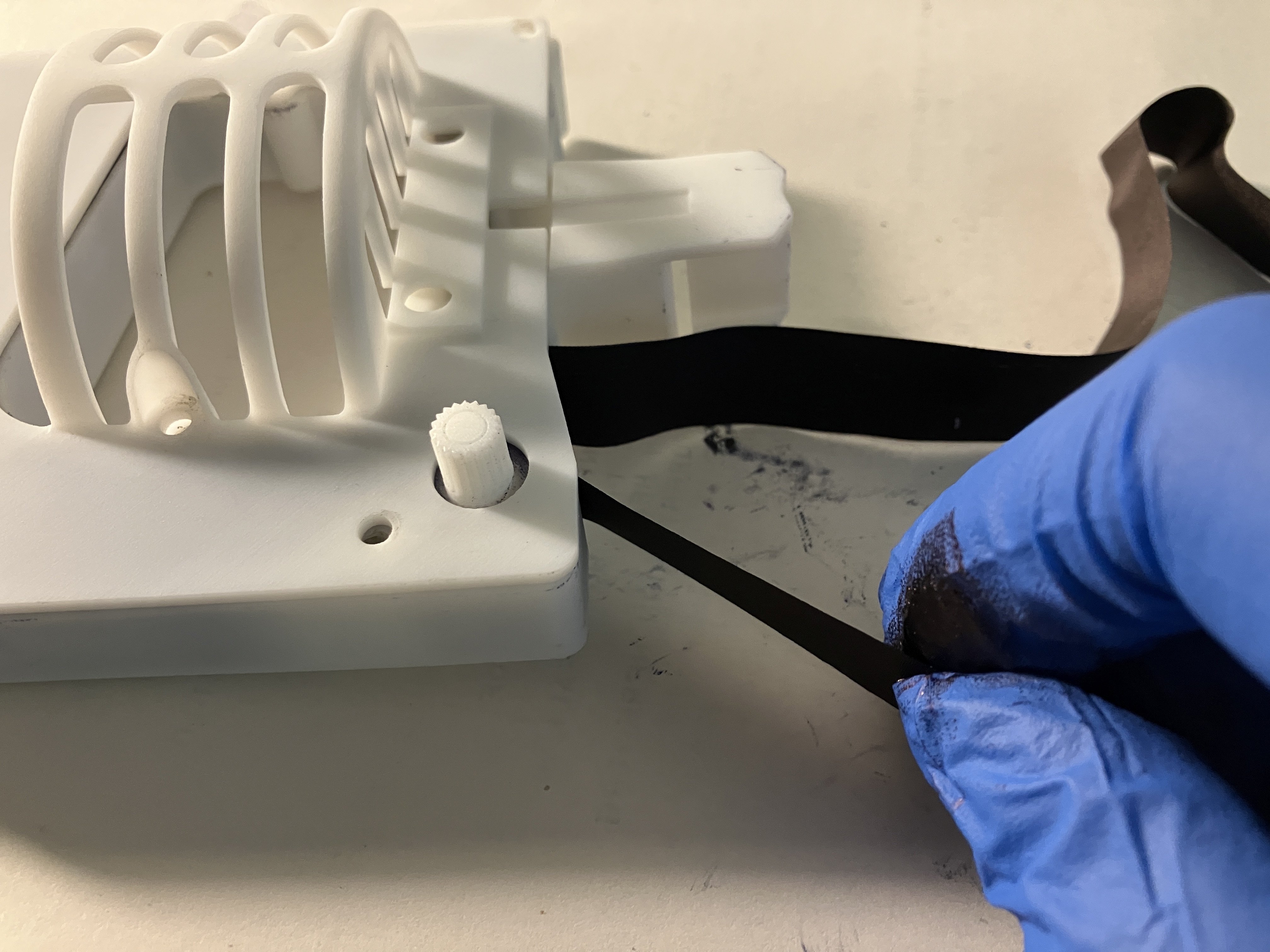
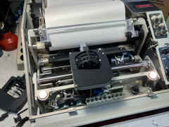
Loop the ribbon through the body and in back of
the headpiece, then guide the ribbon between the gears as you turn the
knob.
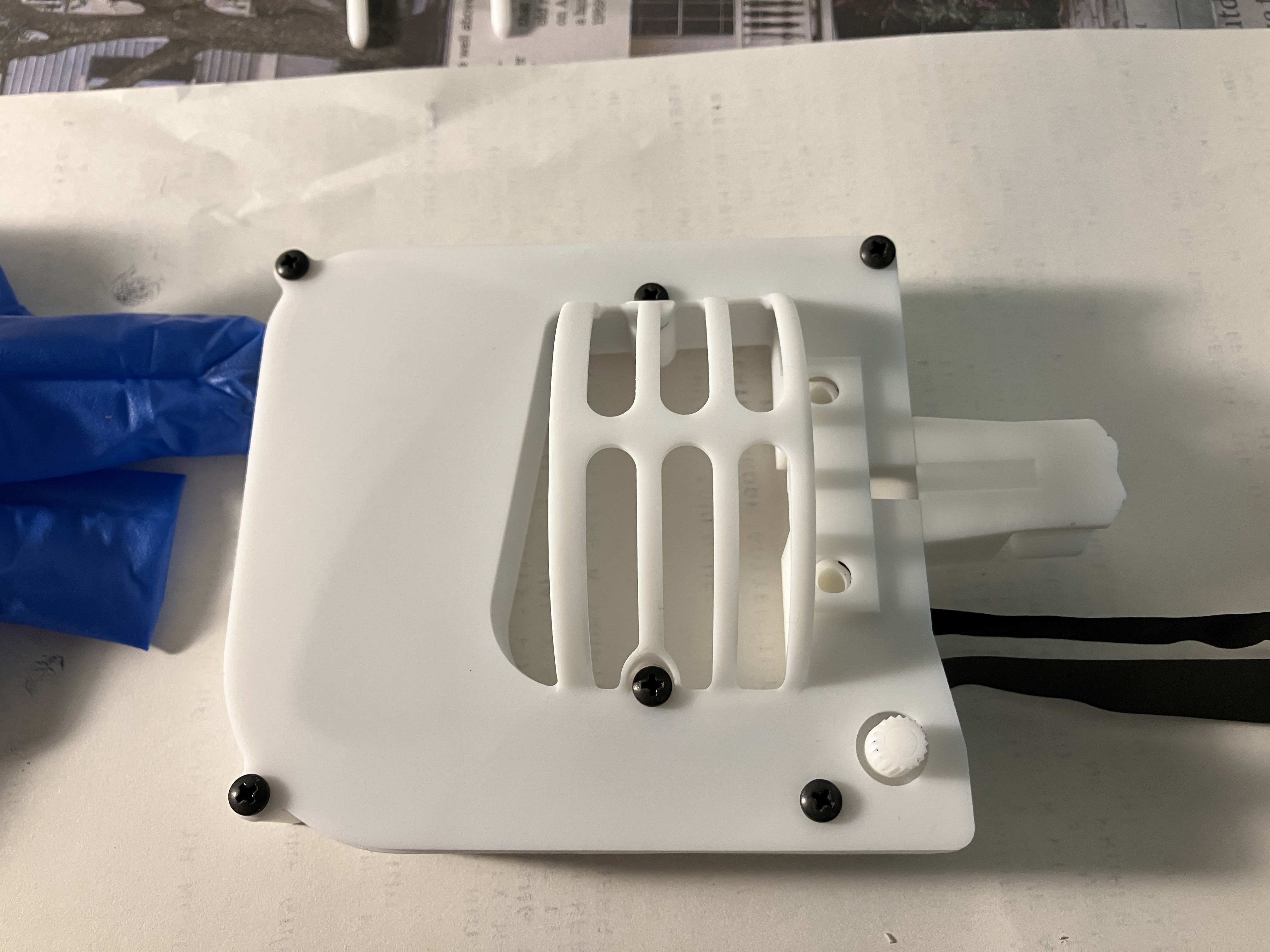
Once the ribbon is fully seated between the gears, you can put the top
cover back on -
CAUTION! Do not overtighten the screws which thread into the
plastic.
If you do, then use a 4-40 x 1/4" or 4-40 x 5/16" screw to
replace the existing 4-40 x 3/16" |
 |
 |

|
== |
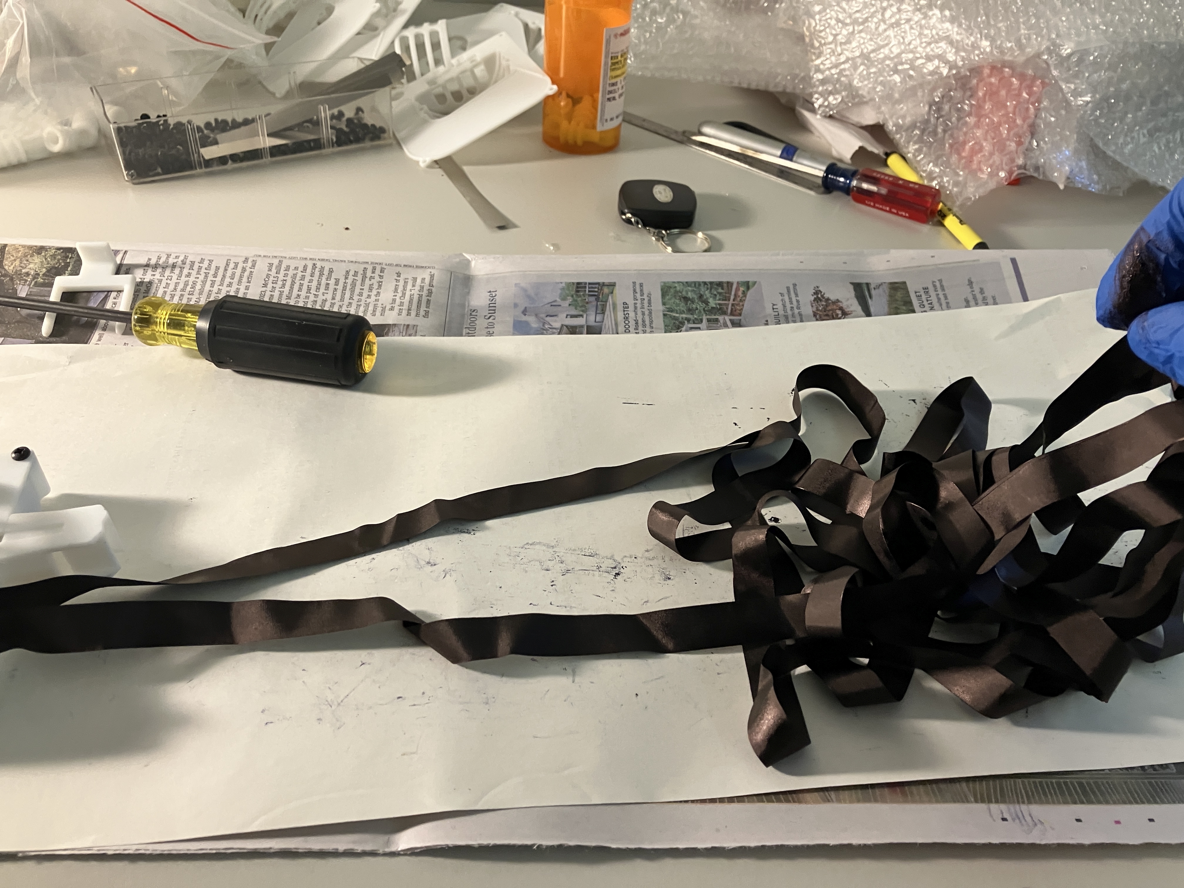
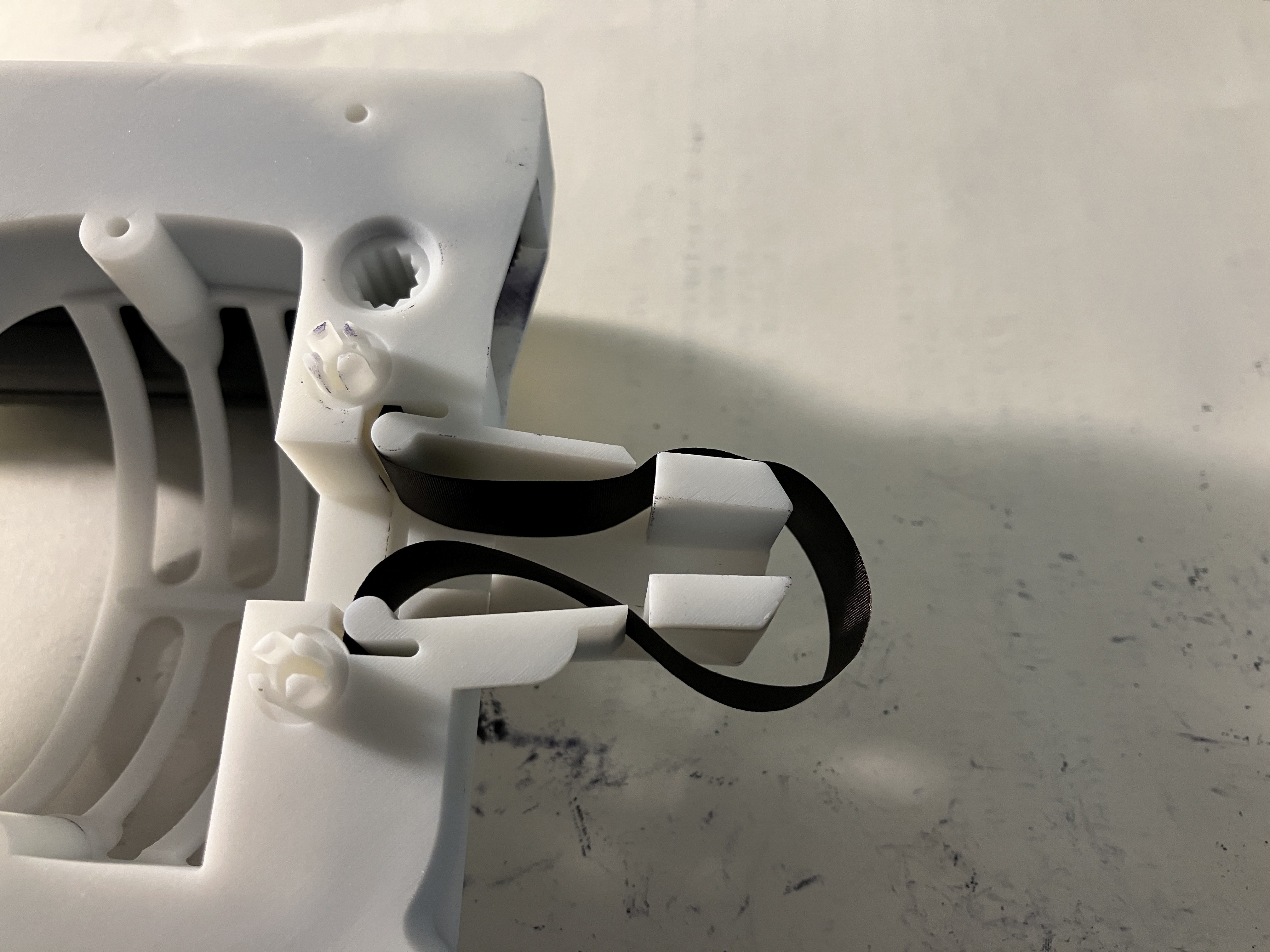
| Guide the ribbon between the gears as you turn
the knob, making sure it doesn't twist - you will have to stop and loosen
the loops of the remaining ribbon |
 |
 |

|
 |
 |
 |
==
|
== |
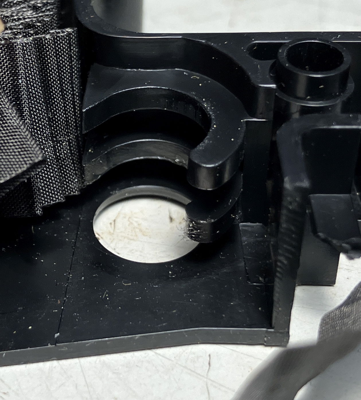
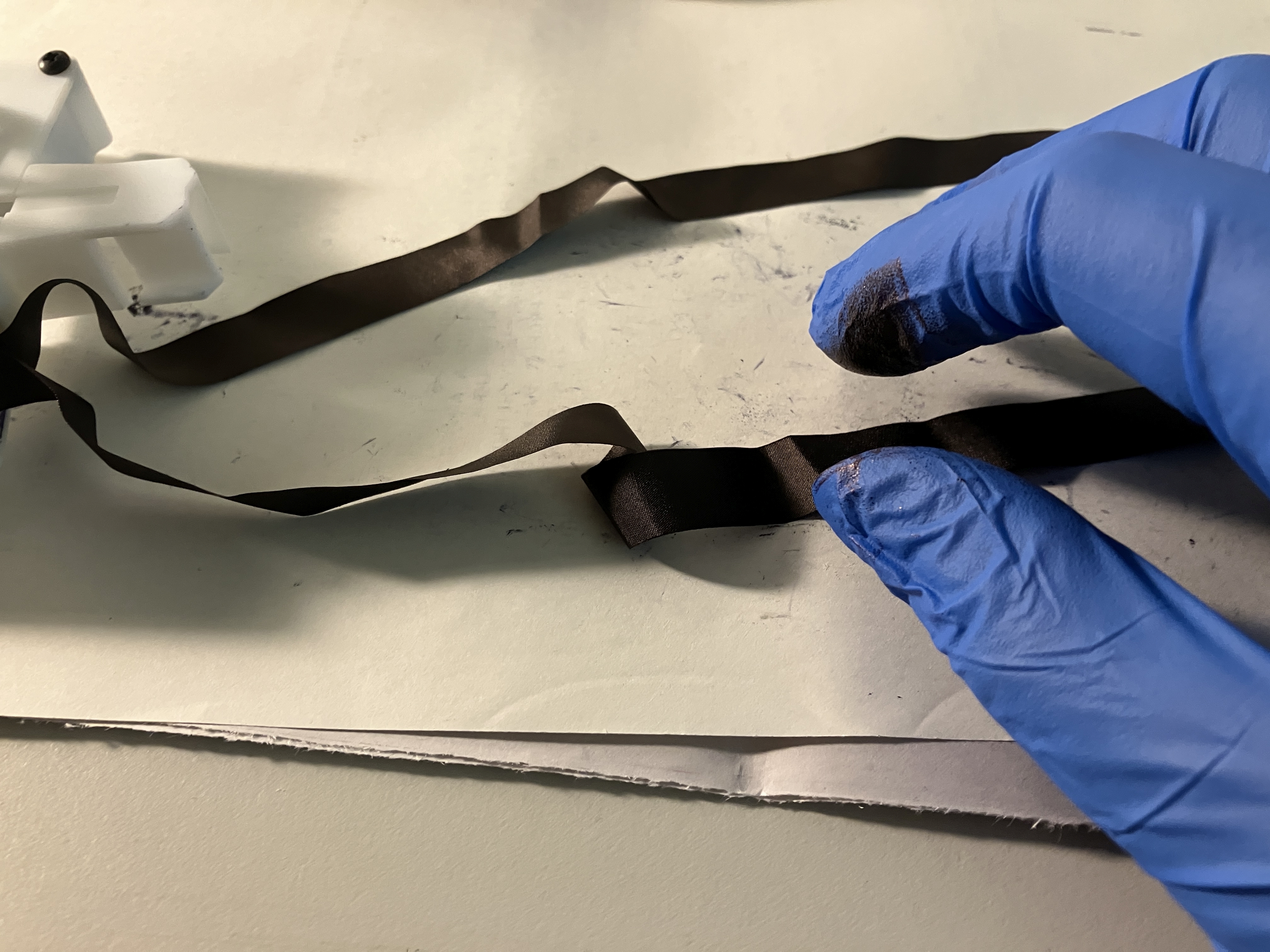
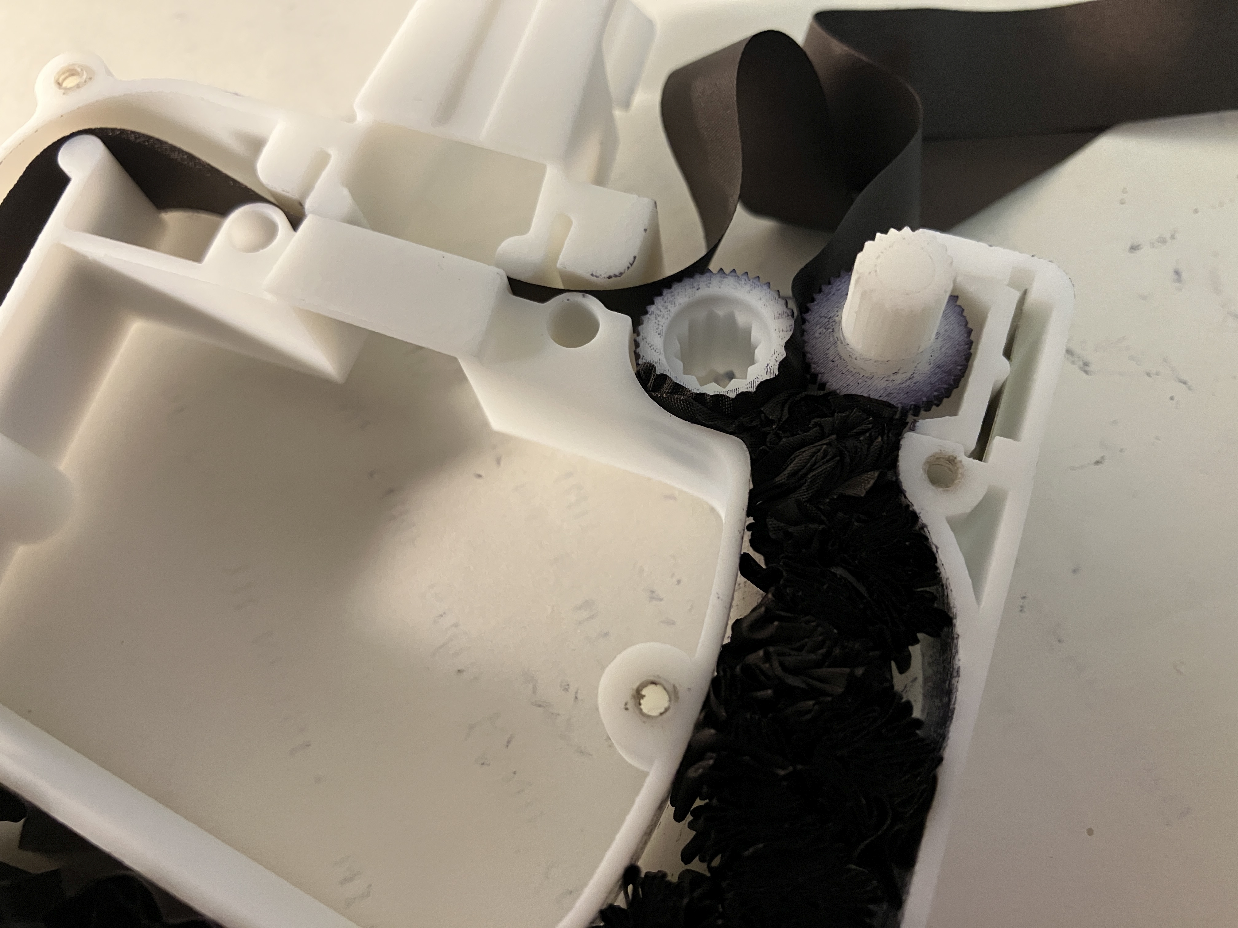
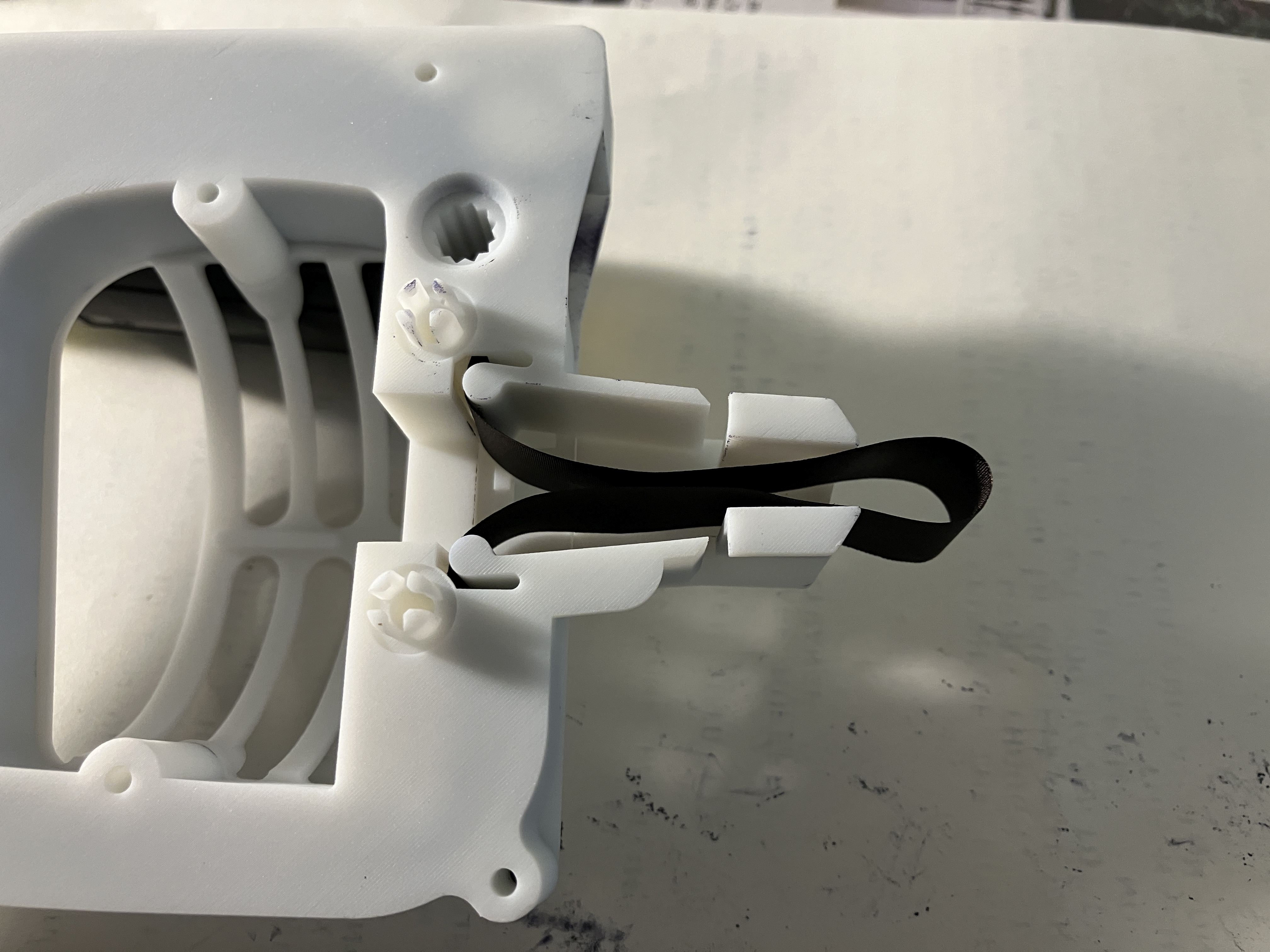
| How to avoid PROBLEM #1 - feed the ribbon at an
angle so that it bears against the manual gear |
 |
== |
==
|
== |
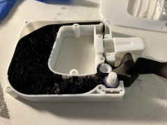
PROBLEM #1 - I let the ribbon wrap around
the drive gear - symptom was that turning the knob went from easy to
almost impossible.
Remove the top and carefully pull some ribbon back out in order to unwrap
it from the drive gear.
While you are in there use your screwdriver blade or something similar to
move the packed ribbon on around within the body cavity. |
 |
 |

|
 |
Finishing Up - turn the knob until all the slack
is taken up. Then use your screwdriver blade or similar to pull a loop
into the headpiece.
Once the loop is in place, turn the knob to take up slack and keep turning
to make sure the ribbon feeds through the headpiece OK, |
 |
 |

|
 |
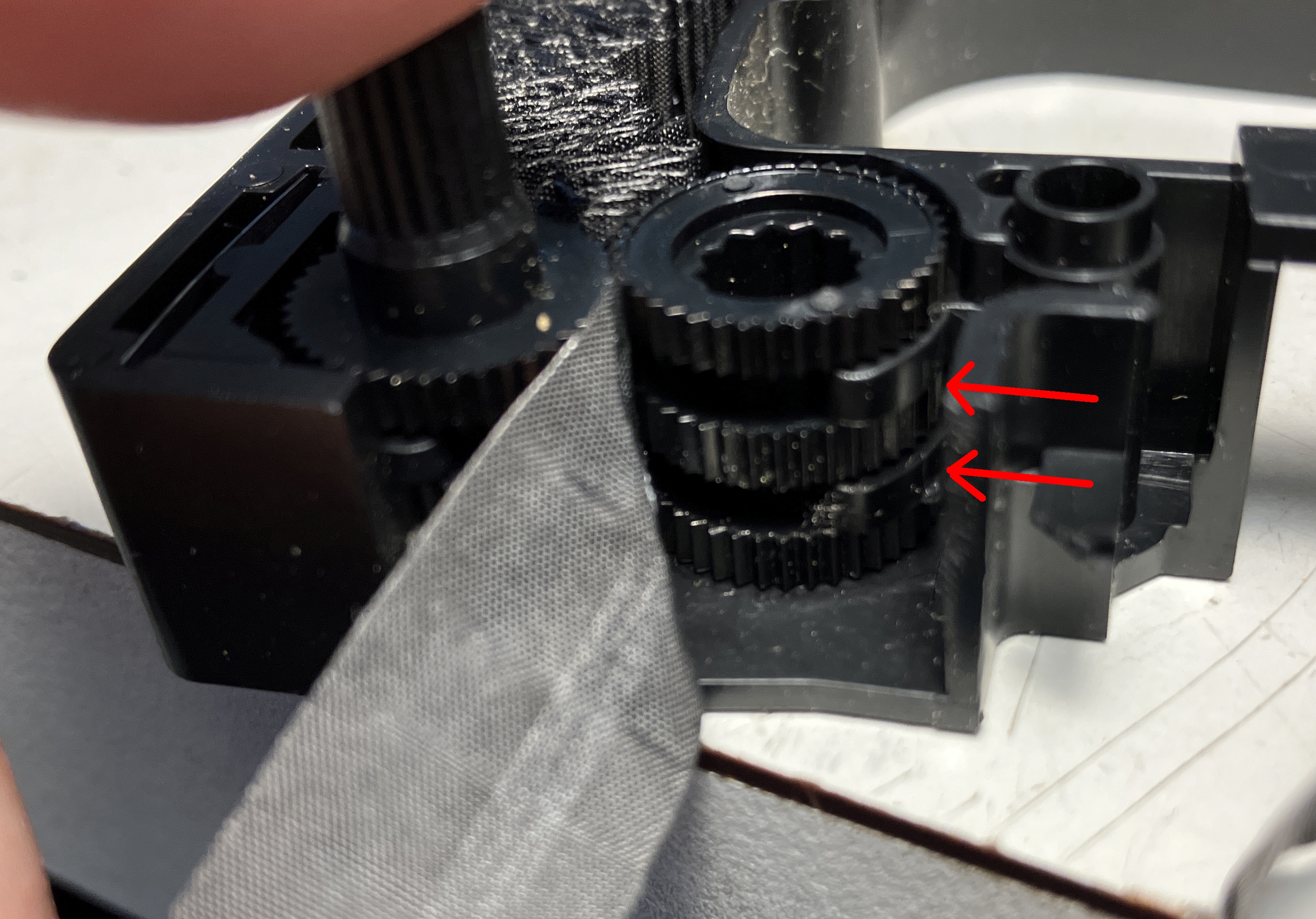
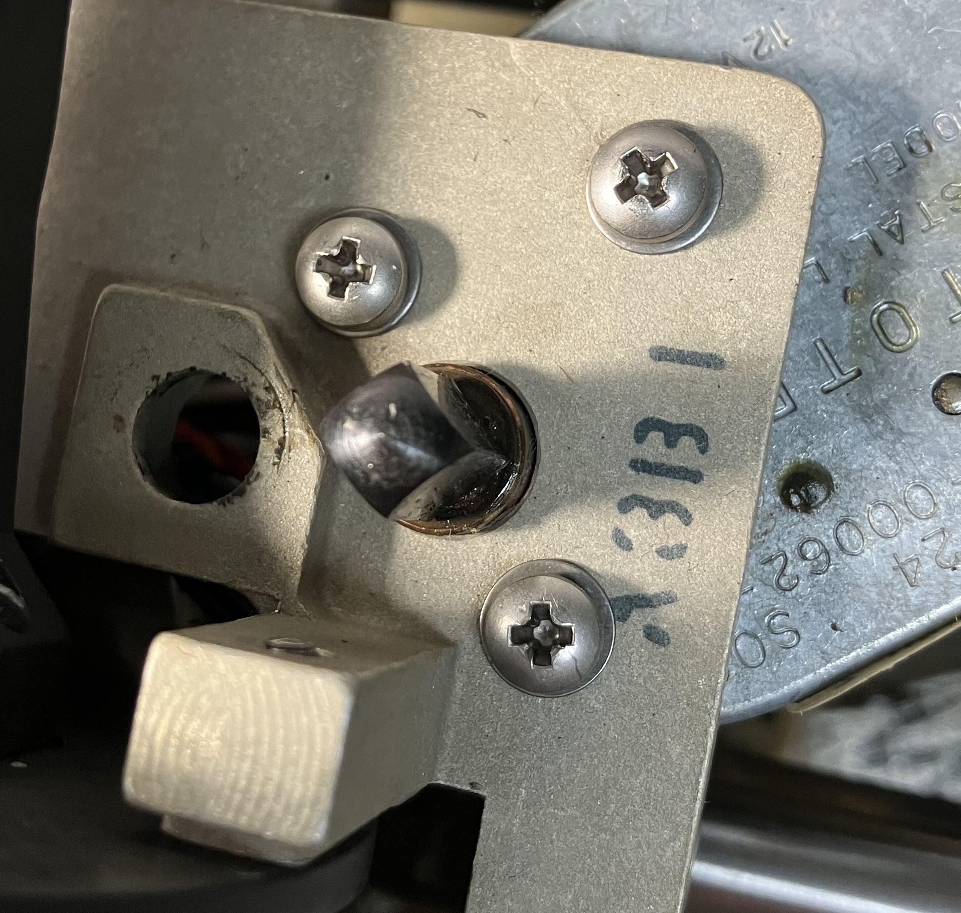
PROBLEM #2 - some of the cartridges have a
looser gear mesh than others. So turning the knob (or drive gear) doesn't
pull the tape.
SOLUTION - insert an additional piece of spring steel to add more gear
mesh tension. Just slide it in place right alongside the existing spring
piece which applies tension to the sliding bracket that cradles the knob
gear..
Put a dot on the knob so you can watch that it is rotating properly as you
are testing and using the cartridge. |
 |
 |

|
Let me know if you need an additional piece of spring steel |