Navy Receiver Accessories -
AF Switchboard, Jack Panel, Audio Amp, & Loudspeaker

sb-interconnect-01.JPG (180053 bytes)
Shipboard Receiver & Transmitter Switchboard Interconnections

RECEIVER RF PATCH PANELS - See Receiving RF Patch Panels & Switches

-

RECEIVER AF PATCH PANELS

Also see Receiver Site AF/RF Signal Distribution Units

NT-49063 Audio Jack for receiver operating positions

jack-49063-1505-01.JPG (159744 bytes) jack-49063-1505-02.JPG (132493 bytes) jack-49063-1505-04.JPG (357254 bytes)

NT-491394 Audio Jack Panel
jack-491394-01.JPG (1354197 bytes)

jack-491394-03.JPG (1436567 bytes)

Two rows of 13-pairs, 2-conductor
jack-491394-02.JPG (1307658 bytes)
jack-491394-05.JPG (1175109 bytes) jack-491394-04.JPG (1327414 bytes)

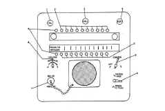
C-443/G AF Control and Jack Box - installed at receiver operating position
c443-g-01.JPG (4035869 bytes)

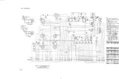
C-443/G schematic  

c443-g-03.JPG (3697627 bytes)

c443-g-05.JPG (3813170 bytes) c443-g-04.JPG (4017510 bytes)

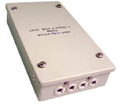
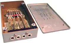
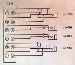
J-939B/U Audio Jack Box - typically installed at receiver operating position


j939b-u-1712-01.jpg (115525 bytes) j939b-u-1712-02.jpg (146747 bytes) j939b-u-1712-03.jpg (219282 bytes)

SB-470/FG Comm station audio patch panel
shore-2-30.JPG (239059 bytes)

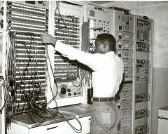
Guam - patch panel
Patchboards at NAVCOMMSTA Guam - Note AN/FCC-3 multiplexer in Rack #14 and TH-39/UGT keyer in Rack #15

Older-style audio patch panels always used dual 2-conductor patch cords - with signal on each tip and shield on the sleeves.
nt91397-01.JPG (138586 bytes)

Also see Receiver Site AF/RF Signal Distribution Units

Newer-style audio patch panels used 3-conductor patch cords, with signal lines on tip and ring, and shield on sleeve. If the transmit-and-receive side of a communications circuit is wired to adjacent jack fields, a dual patch-cord assembly may be used to patch both sides of the circuit simultaneously.

SB-3092/U audio patch panel
sb3092a-1311-01.jpg (244255 bytes)

sb3092a-1311-03.jpg (254080 bytes)

These are 3-conductor jacks - signal lines are on tip and ring, shield on sleeve.
sb3092a-1311-02.jpg (445766 bytes)
sb3092a-1311-04.jpg (553389 bytes) sb3092a-1311-05.jpg (219299 bytes)

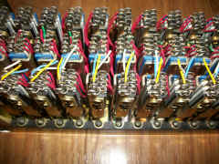
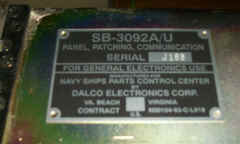
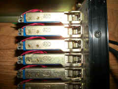
COMMUNICATIONS PATCH PANEL, SB-3092A/U - This is an audio circuit communications patch panel. It has three rows of 26 jacks, each mounted on an open frame suitable for installation on a 19-inch rack. Connections to the panel are facilitated by a terminal block mounted at the rear of the frame (missing in photos above)
    The three rows of jacks are labeled monitor (MON), LINE, and equipment (EQUIP). The MON jacks are wired parallel to the LINE jacks. The LINE jacks are wired directly to the audio source, and the EQUIP jacks are wired to the load or equipment using the audio signal. Under normal conditions, with no patch cords inserted into a jack field, the audio source is wired directly through the audio load. When a patch cord is inserted into a LINE jack, the audio source is removed from the load connected to the EQUIP jack located directly below the LINE jack, and the source now appears at the other end of the patch cord. When this end of the cord is inserted into an EQUIP jack, the audio source appearing on the LINE jack directly above the EQUIP jack is removed from the load, and an alternate circuit has been completed between the two ends of the patch cord. The MON jacks allow the operator to test an audio circuit without disturbing signal flow by inserting a patch cord between the appropriate MON jack and another jack connected to the input of the desired piece of test equipment. The patch panel can accommodate up to 26 audio circuits. If the transmit-and-receive side of a communications circuit is wired to adjacent jack fields, a dual patch-cord assembly may be used to patch both sides of the circuit simultaneously.

NT-491397
nt91397-01.JPG (138586 bytes)
24" patch cord with
NT-491242 plugs
What numbers for other lengths?  manuf CN-491242 
manuf CN-491397
National Electric Machine
--

AF Level Meters

ID-1185/FRA
id1185-fra-06.JPG (62233 bytes)
AF level meter + amp & speaker
id1185-fra-07.JPG (84778 bytes) id1185-fra-09.JPG (99789 bytes) Used in COMMSTA AF/RF Signal Distribution Unit 

transistorized - note - schematic is printed on bottom cover

TS-629B/U
ts629-u-1212-01.JPG (88828 bytes)

ts629-u-1212-05.JPG (112536 bytes)

AF level meter

ts629-u-1212-04.JPG (111389 bytes)

ts629-u-1212-03.JPG (43181 bytes) Used in COMMSTA AF/RF Signal Distribution Unit - barely visible at upper left of Guam photo above.

octal tubes - note - schematic is inside unit

Manual for TS-629A/U

ts629b-u-02.JPG (52112 bytes)

ts629b-u-04.JPG (69359 bytes)

ts629b-u-03.JPG (55837 bytes) ts629b-u-05.JPG (99245 bytes) --
--

RECEIVER AF TRANSFER SWITCHBOARDS

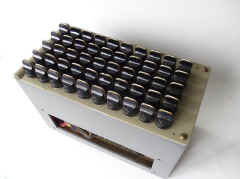
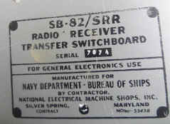
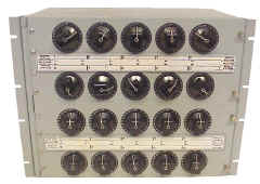
SB-82/SRR
sb82-103.jpg (16321 bytes)
AF switching
10 remotes, 5 receivers
(10 outputs, 5 inputs)

sb82-101.jpg (11504 bytes)

sb82-1402-02.jpg (63427 bytes)   SB-82/SRR  manual  

  Spec Sheet - thanks to HNSA

sb82-1103-01.JPG (371177 bytes)

sb82-1402-01.jpg (82615 bytes) sb82-1402-05.jpg (112676 bytes) sb82-1402-04.jpg (59717 bytes) sb82-1402-03.jpg (91133 bytes)
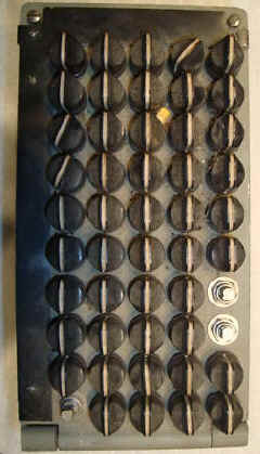
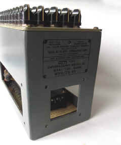
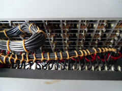
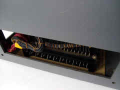
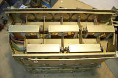
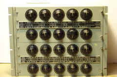
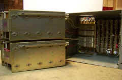
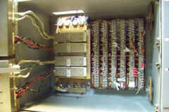
    Receiver transfer switchboard, type SB-82/SRR, is shown above. The receiver switchboard has five vertical rows of ten single-throw (ON-OFF) switches that are continuously rotatable in either direction. One side of each switch within a vertical row is wired in parallel with the same sides of the other nine switches within the row. Similarly, the other side of each switch is wired in parallel horizontally with the corresponding sides of each of the other four switches in a horizontal row. This method of connecting the switches permits a high degree of flexibility.
    In general, there are more remote stations than radio receivers, hence the audio outputs five receivers are fed to the five vertical rows and ten remote stations are connected the ten horizontal rows. With this arrangement, a selected receiver output is connected to any or all of the remote stations by closing the proper switch(es). When one switchboard is inadequate for accommodating all of : receivers and remote stations installed in ship, several of these switchboards are mounted together and interconnected so that they form a bank of switchboards. 
    The knob of each switch is marked with heavy white line to provide visual indication of whether the switch is in the ON or OFF position Switchboards always are installed with the line positioned vertically when the switch is open (off). To further standardize all installations, receivers usually are connected to the vertical rows of switches, and remote stations are connected to the horizontal rows. Identification of the receivers and remote stations is engraved on the laminated bakelite label strips fastened along the top and left edges of the panel front.
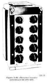
SB-973/SRR
3-48.jpg (57084 bytes)
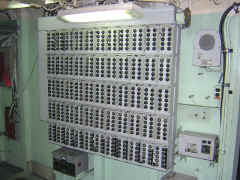
SB-973/SRR aboard DLG-30
dlg30-radioswitch.jpg (150391 bytes)

sb973-1411-01.JPG (160258 bytes)

sb973-1411-03.JPG (232365 bytes)

sb973-1411-02.JPG (161657 bytes)
sb973-1411-04.JPG (193784 bytes) sb973-1411-05.JPG (266801 bytes) sb973-1411-06.JPG (320145 bytes) sb973-1411-07.JPG (215200 bytes)
SB-973/SRR - AF switching - 10 remotes, 5 receivers
   A more recent model receiver transfer switchboard is the SB-973/SRR, illustrated above. This switchboard contains 10 seven position rotary selector switches. Each switch or operating knob relates to a remote control station Switch positions one through five relate to receivers.
    Position X on each switch serves to transfer the remote control stations connected to the original switchboard to the corresponding switches in additional switchboards. In this manner, any number of receivers can be connected to the ten remote control stations. An additional switchboard is needed for each five additional receivers.
    Switchboards providing facilities for additional remote control stations are mounted in vertical sequence, whereas those containing additional receivers are mounted in horizontal sequence.
SB-2727/SRR
sb2727-01.jpg (56777 bytes)
AF switching
20 remotes, 24 receivers

sb2727-srr-52.jpg (50991 bytes)

sb2727-srr-54.jpg (53058 bytes) NAVSHIPS 0969-124-8010

 download pdf manual

sb2727-srr-51.jpg (58788 bytes) sb2727-srr-53.jpg (44564 bytes) sb2727-srr-55.jpg (57922 bytes) -

AUDIO AMPLIFIERS & LOUDSPEAKERS

AM-215/U
AM-215A/U
AM-215B/U
AM-215C/U
AM-215D/U
audio amp

5 inputs, 10 watts output

am215a-u-01.JPG (172182 bytes)
photo thanks to Dave Guggenheim

AM-215 Info Page - Photos and Spec Sheets for all models

The AM-215( )/U is an audio amplifier unit that amplifies low-level audio signals for reproduction through loudspeakers. As many as five radio receivers and five loudspeakers can be connected to this unit, but only one signal is amplified and reproduced at any one time. The signal to be amplified and reproduced is selected by means of a channel selector switch located on the front of the amplifier unit. Other controls on the unit's front panel are a volume control, a power on-off switch, and a power-on indicating lamp.

AM-215B/U, AM-215C/U, AM-215D/U manual - NAVSHIPS 91626 pdf

AM-413/G
AM-413A/G
audio amp & compressor

Adjustment procedure and info

AM-413/G manual download

am413-g-91.JPG (86157 bytes) am413-g-92.JPG (72570 bytes) Manuf - 
  Harmon-Kardon AM-413/G
  Amer. Measuring Instrument - AM-413A/G


am413a-g-0211-1300.jpg (10478 bytes)

am413a-g-0211-1301.jpg (29506 bytes) am413a-g-0211-1302.jpg (44861 bytes) am413a-g-0211-1303.jpg (38287 bytes)

AM-3729/SR audio amp
am3729-sr-1301-01.JPG (537126 bytes)

transistorized replacement for AM-215/U - Manual

am3729-1901-01.jpg (232577 bytes)

am3729-1901-03.jpg (480570 bytes) am3729-1901-04.jpg (403889 bytes)

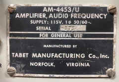
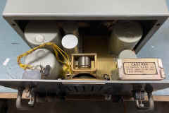
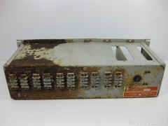
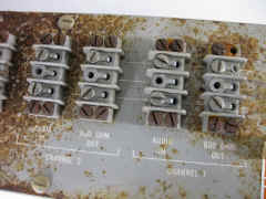
AM-4453/U
am4453-dj-04.jpg (164952 bytes)

Speaker-Amp - Specs
5 input, 10 watt, transistorized
Manual

Photos and manual thanks to Daniel K6YIC


am4453-dj-02.jpg (190030 bytes) am4453-dj-03.jpg (179293 bytes)

AM-6222/U
AM-6223/U
audio amp
am6223-u-1103.JPG (11734 bytes)

am6223-u-1102.JPG (19981 bytes) am6223-u-1100.JPG (96936 bytes) am6223-u-1101.JPG (86178 bytes)

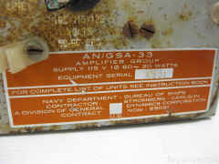
AN/GSA-33
audio amp & compressor
gsa33-01.jpg (21763 bytes)

Amplifier Group
5 channel compressor

AM-1910/G amplifiers
PP-2310/G power supply

Adjustment procedure and info

gsa33-02.jpg (22434 bytes)

Manuf Melcor

NAVSHIPS 93433

Please send me email if you have a manual I can borrow/buy

gsa33-1309-01.JPG (284234 bytes)

gsa33-1309-02.JPG (329457 bytes) gsa33-1309-03.JPG (299428 bytes) --

gsa33-1203-01.jpg (90269 bytes)

gsa33-1203-02.jpg (94671 bytes) gsa33-1203-10.jpg (286920 bytes) gsa33-1203-04.jpg (259604 bytes)

gsa33-1203-05.jpg (217764 bytes)

gsa33-1203-06.jpg (221308 bytes) gsa33-1203-07.jpg (194019 bytes) --

gsa33-1203-08.jpg (192580 bytes)

gsa33-1203-09.jpg (209709 bytes) gsa33-1203-03.jpg (135677 bytes) --

RMHP 22C-102
5 channel audio attenuator
af-atten-01.JPG (1288025 bytes)

shipyard built item
aboard USS Midway
-- --
--

Communications Loudspeakers & Amplifier-Loudspeakers

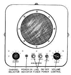
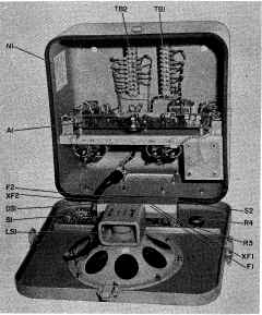
AM-2631/U Amplifier-Loudspeaker

general purpose speaker with built-in audio amp. Five input channels, 5 watts.
Replacement for NT-49545

manual

am2631-1911-03.JPG (3893182 bytes) am2631-1911-01.jpg (404284 bytes) am2631-1911-02.jpg (2408852 bytes)

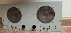
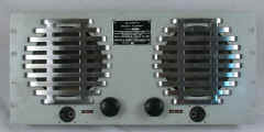
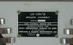
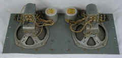
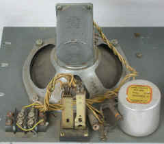
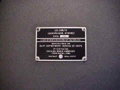
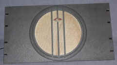
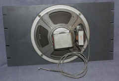
LS-139/G

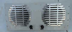
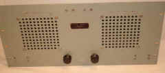
Rack mount twin speaker
used in Comm Stations

ls139-g-41.jpg (37241 bytes)

ls139-g-21.jpg (38467 bytes)

Version without phone jacks
Manuf Westlab & others
ls139-g-1303-02.jpg (127537 bytes)

Version with phone jacks
manuf Airplane & Marine Instruments
ls139-g-42.jpg (45165 bytes)

Another version 
(DSA, not USN - manuf Adek)
ls139-g-31.jpg (29302 bytes)

ls139-g-34.jpg (44571 bytes)

ls139-g-32.jpg (9226 bytes)

Another version (not USN)
ls139-mys-2103-01.jpg (263133 bytes)

ls139-mys-2103-02.jpg (250986 bytes)

ls139-mys-2103-03.jpg (24868 bytes)

ls139-g-1308-01.JPG (317026 bytes) ls139-g-1308-03.JPG (525836 bytes) ls139-g-1308-02.JPG (488558 bytes)

ls139-g-1303-01.jpg (182335 bytes)

NAVSHIPS 93095

ls139g-91.jpg (34714 bytes) ls139g-92.jpg (39125 bytes) ls139g-93.jpg (30878 bytes) ls139g-95.jpg (55488 bytes)

LS-169/G

manual download (includes AM-413/G)

 A single-speaker version of the LS-139/G ls169g-01.jpg (126939 bytes) ls169g-02.jpg (96929 bytes)

LS-195/U
ls195-1306-01.JPG (337951 bytes)

   A general-purpose communication loudspeaker is the LS-195/U. Like the NT-49546, this unit is used mainly for monitoring voice channels. Unlike the NT-49546, however, the unit cannot withstand prolonged exposure to the weather; it is designed for installation in protected areas only. In addition, it has a front panel volume control and is transportable, whereas the NT-49546 has a preset, covered volume control and is mounted permanently.

ls195-1306-05.JPG (383524 bytes) ls195-1306-02.JPG (374994 bytes) ls195-1306-07.JPG (508114 bytes) ls195-1306-03.JPG (393143 bytes)
ls195-1904-01.jpg (181942 bytes) ls195-1904-02.jpg (159947 bytes) ls195-1904-03.jpg (157618 bytes) ==

LS-199/U (for AN/URR-23A)
ls199-1412-01.jpg (126464 bytes)

ls199-1412-02.jpg (163572 bytes) LS-228/U (for AN/URR-39)
ls228-u-91.jpg (74855 bytes)
ls228-u-92.jpg (60729 bytes)

LS-474/U
ls474-u-01.jpg (23533 bytes)

ls474-int.JPG (1839939 bytes) Manuf Fidelity Amplifier

ls474u-95.jpg (257895 bytes)

spkr-ls474-cv41-01.JPG (3036314 bytes)
LS-474/U + AM-3729/SR amplifier aboard USS Midway

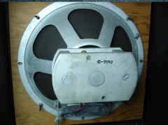
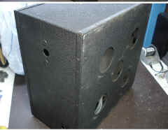
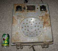
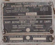
CMX-49131 amplifier-loudspeaker
spkr-CMX49131C-1210-01.JPG (467291 bytes)

Information - specs

Schematic & Parts List

spkr-CMX49131C-1210-02.JPG (376933 bytes)

Manuf Magnavox

spkr-CMX49131C-1210-03.JPG (295763 bytes)

spkr-CMX49131C-1210-04.JPG (657007 bytes)
spkr-CMX49131C-1210-05.JPG (539833 bytes) spkr-CMX49131C-1210-06.JPG (599259 bytes) spkr-CMX49131C-1210-07.JPG (311320 bytes) spkr-CMX49131C-1210-08.JPG (362305 bytes)
spkr-CMX49131C-1210-09.JPG (336312 bytes) spkr-CMX49131C-1210-10.JPG (606975 bytes) == ==

CMX-49155 (for TBS)
spkr-tbs-49155-120401.JPG (311130 bytes)


spkr-tbs-49155-120402.JPG (502633 bytes) spkr-tbs-49155-120403.JPG (551301 bytes) ==

CMX-49545 amplifier-loudspeaker

spkr-49545-1208-01.jpg (126428 bytes)

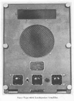
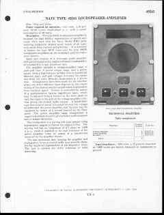
    The Navy type 49545 amplifier-speaker unit is a combination audio amplifier and loudspeaker assembly. Its reproduction qualities are considered good. Aboard most ships, it is installed in berthing and messing compartments as an entertainment loudspeaker.
    All operating controls of the unit are located on the front panel. They consist of a power on-off switch, a power-on indicating lamp, a tone control, a volume control, and a channel selector switch that permits selection of up to five different entertainment (or communication) channels.

Manual NAVSHIPS 900,853 download

spkr-49545-1301-1.JPG (162563 bytes) spkr-49545-1301-2.JPG (148217 bytes) spkr-49545-1301-4.jpg (76227 bytes) spkr-49545-1301-3.jpg (92859 bytes)
       

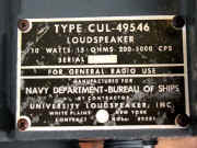
NT-49546 Loudspeaker

Specifications

cul45946-10.jpg (136380 bytes)

cul45946-12.jpg (24098 bytes) general radio use
manuf CUL University
manuf Tabet
cul45946-11.jpg (50453 bytes)
49546-int-01.JPG (5290377 bytes)
spkr-49546-1505-01.JPG (224180 bytes) spkr-49546-1505-03.JPG (197675 bytes) 49546-schem-02.jpg (921061 bytes) 49546-schem-01.jpg (757436 bytes)
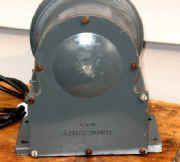
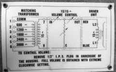
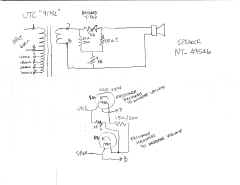
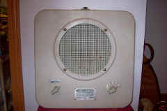
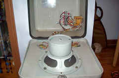
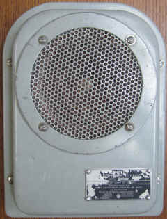
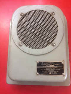
Although it is a general-purpose communication loudspeaker, the NT-49546 is used principally for reproducing voice transmissions. The unit can be connected directly to a radio receiver, or it can be operated through an audio amplifier unit, such as the AM/215( )/U. Best results are obtained with the audio amplifier unit. The loudspeaker, designed as a watertight and shockproof unit for installation in exposed areas, also is used extensively in such spaces as the pilothouse and CIC. It usually is mounted on the bulkhead above or near its controlling amplifier unit.

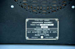
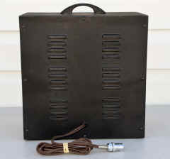
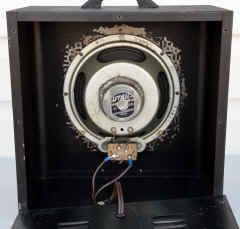
CZY-49583
spkr-49583-1511-01.jpg (255891 bytes)

spkr-49583-1511-02.jpg (297408 bytes)

manuf CZY Allied Radio

spkr-49583-1511-05.jpg (280695 bytes) spkr-49583-1511-04.jpg (226095 bytes)

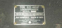
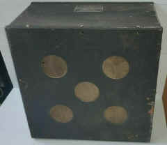
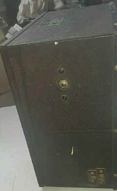
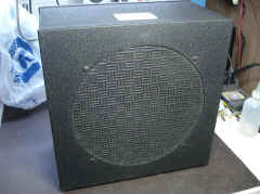
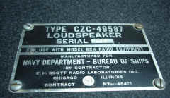
CZC-49587 (used with RCH)

spkr-49587-rch-2001-01.jpg (95580 bytes)

spkr-49587-rch-2001-02.jpg (168356 bytes)

spkr-49587-rch-2001-03.jpg (77987 bytes)

spkr-49587-rch-2001-04.jpg (54428 bytes) spkr-49587-rch-2001-05.jpg (96909 bytes)
spkr-49587-1120-01.jpg (801903 bytes) spkr-49587-1120-02.jpg (668833 bytes) spkr-49587-1120-03.jpg (510451 bytes) spkr-49587-1120-04.jpg (904492 bytes)

CMX-49620  amp/speaker
cmx49620-01.jpg (41130 bytes)

spkr-nt49620-1103.jpg (111588 bytes)

Amp & 8" Speaker

cmx49620-102.jpg (41005 bytes)

cmx49620-02.jpg (27449 bytes)
cmx49620-103.jpg (127307 bytes) cmx49620-108.jpg (14826 bytes)

cmx49620-106.jpg (9692 bytes)

manuf CMX Magnavox-

cmx49620-105.jpg (92441 bytes)

spkr-nt49620-1105.jpg (141539 bytes) spkr-nt49620-1107.jpg (35166 bytes) spkr-nt49620-1109.jpg (113030 bytes) --
spkr-49620-1402-01.JPG (390106 bytes) spkr-49620-1402-02.JPG (223074 bytes)

spkr-49620-1402-06.JPG (302826 bytes)

spkr-49620-1402-03.JPG (488892 bytes) spkr-49620-1402-04.JPG (401889 bytes)

CCI-491120
spkr-491120-1603-01.jpg (460093 bytes)

spkr-491120-1603-02.jpg (477699 bytes) spkr-491120-1603-03.jpg (438423 bytes) ==

General Purpose & PA loudspeakers (Interior Communications)

AM-2320A/WIC amplifier-loudspeaker
spkr-am2320a-wic-1411-05.JPG (208937 bytes)
spkr-am2320a-wic-1411-01.JPG (325432 bytes) spkr-am2320a-wic-1411-02.JPG (178462 bytes) spkr-am2320a-wic-1411-04.JPG (187639 bytes)
LS-305/SIC
ls305-sic-01.jpg (6640 bytes)
ls305-sic-02.jpg (13381 bytes)
70v line input. Transformer taps give up to -24dB attenuation
ls305-sic-03.jpg (6483 bytes) manuf Tabet, Dynalec

Download spec sheet

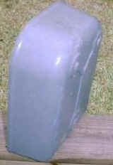
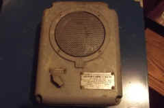
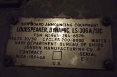
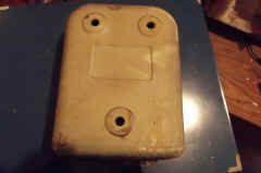
LS-306A/SIC
ls306a-sic-1207-01.jpg (289085 bytes)
ls306a-sic-1207-02.jpg (286249 bytes) ls306a-sic-1207-03.jpg (238599 bytes) ==
LS-388/SIC
ls388-sic-01.jpg (59768 bytes)
ls388-sic-02.jpg (64355 bytes)
70v line
ls388-sic-03.jpg (68726 bytes) ls388-sic-04.jpg (58902 bytes)

LS-444/WIH, LS-443/WIH

ls444-wih-1308-1.JPG (62282 bytes)

Manual - thanks to K7HUE


ls444-wih-1308-2.JPG (56036 bytes) ls444-wih-1308-3.JPG (39219 bytes)

ls444-xfmr-02.jpg (66831 bytes)

ls444-wih-1911-02.JPG (2648866 bytes)
LS-519/SIC
ls519-sic-01.jpg (66343 bytes)
ls519-sic-02.jpg (232363 bytes)    
LS-530/SIC
ls530-sic-50.JPG (77135 bytes)
ls530-sic-51.JPG (78578 bytes)
70v line input
ls530-sic-52.JPG (42589 bytes) manuf Telectro Systems
LS-543/SIC
ls543-sic-01.jpg (19720 bytes)
ls543-sic-02.jpg (21862 bytes) - manuf University
RCA MI-2915-FA
spkr-MI-2915-FA-01.jpg (18786 bytes)
spkr-MI-2915-FA-02.jpg (18711 bytes) spkr-MI-2915-FA-03.jpg (9912 bytes) manuf RCA
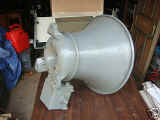
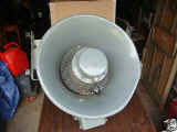
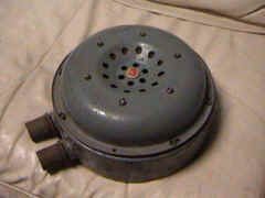
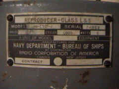
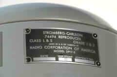
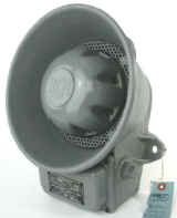
RCA MI-2917-J
spkr-mi2917j-01.jpg (52938 bytes)
spkr-mi2917j-02.jpg (52033 bytes) spkr-mi2917j-03.jpg (55347 bytes) manuf RCA
RCA 2917-S
spkr-74404-1207-01.jpg (206610 bytes)
spkr-74404-1207-04.jpg (166089 bytes) spkr-74404-1207-05.jpg (367389 bytes) manuf RCA
spkr-74404-1207-03.jpg (214441 bytes)
RCA MI-2961
MI-2961-01.jpg (20551 bytes)
MI-2961-02.jpg (16414 bytes) - manuf RCA
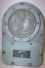
Jensen NA-10001
na10001-spkr-01.jpg (10496 bytes)
na10001-spkr-03.jpg (16382 bytes) na10001-spkr-02.jpg (11157 bytes) manuf Jensen
VRS-1 recording equipment
spkr-vrs1-01.JPG (166917 bytes)
spkr-vrs1-02.JPG (106783 bytes) spkr-vrs1-03.JPG (166794 bytes) ==

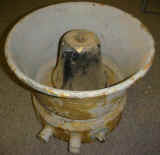
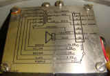
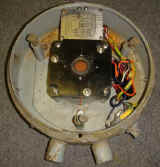
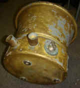
Speakers for use with Underwater Sound Equipment

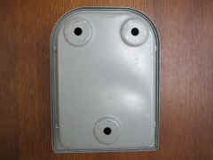
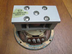
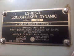
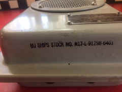
LS-185/U for AN/SQS-1 Sonar
ls185-u-1303-01.jpg (477774 bytes)
ls185-1804-01.jpg (48286 bytes) ls185-u-1303-02.jpg (338274 bytes) ls185-u-1303-03.jpg (384453 bytes)
ls185-1804-02.jpg (40667 bytes) ls185-1804-03.jpg (32048 bytes) manuf Dumont ==
CRV-49145 for NMC equipment
spkr-49145-1404-01.JPG (163308 bytes)
spkr-49145-1404-02.JPG (140861 bytes) spkr-49145-1404-03.JPG (158170 bytes) spkr-49145-1404-04.JPG (239474 bytes)
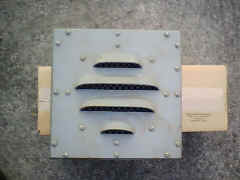
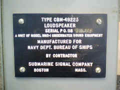
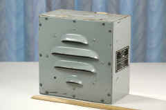
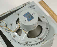
CBM-49225 for NMC-1 equipment
spkr-cbm49225-02.jpg (69327 bytes)
spkr-cbm49225-01.jpg (71883 bytes) == ==
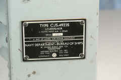
CJS-49235 for QJB Sonar
spkr-49325-1207-01.jpg (21212 bytes)
spkr-49325-1207-02.jpg (36128 bytes) spkr-49325-1207-03.jpg (23913 bytes) ==