
looks on as ET3 P.A. LaClaire operates the code perforator machine. To right, RM2 Claude Cole, Jr. receives teletype tape from another machine.

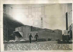
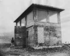
World's strongest transmitter reaches ships anywhere at sea. When Marconi tapped out the world's first wireless message 58 years ago, the weakly transmitted signal carried only to the other side of his garden. Last week, dedicating the most powerful transmitter in the world, The US Navy broadcast a test message which circled the globe. Within minutes acknowledging answers flashed back from a battleship off Japan, a carrier in the western Pacific, and a submarine far off in the Atlantic
The giant transmitter, located 5 miles from Seattle in the Jim Creek valley of Washington's Cascade mountains, is a $14 million wonder which took six years to complete and changed the face of the surrounding wilderness. There, in an area still inhabited by cougar and bear, engineers cleared 2000 acres of heavily wooded slopes, built 12 miles of access roads, and erected permanent housing for 48 Navy men and their families.
The massive electronic equipment, designed and built by RCA, uses as much power as a city of 25,000 population. Its output - 1.2 million watts - makes it 22 times more powerful than any commercial radio station in the U.S.
Most Powerful Transmitter Procured by Bureau of Ships
After a little more than seven years of planning, design, and construction, the Bureau of Ships
has completed its assignment from the Chief of Naval Operations to procure a high-power, low-frequency
radio transmitter and to select a site from which such a radio "voice" could transmit messages
instantaneously to all naval operating units located throughout the world.
On 18 November 1953 a 1,000,000-watt transmitter, located at Jim Creek Valley in the Cascade Mountains of Washington, 55 miles northeast of Seattle and 20 miles inland from Puget Sound, went into operation. It is the most powerful transmitter in the world, having an output more than twice that of any existing military transmitter and 20 times greater than any United States commercial radio station.
Operating on a very low frequency, close to the border line where radio signals begin, the Jim Creek transmitter can flash radio signals to Navy forces or establishments operating in any of seven seas. Signals will penetrate to submarines cruising below the surface.
Puget Sound Area Chosen
This transmitter also insures reliable arctic communication despite frequent magnetic
storms and ionospheric disturbances. The combination of high power and very low frequency means that
the transmitter's broadcast is far less affected by interference, jamming, and irregular wave
propagation than the normally employed high frequencies. It will also overcome
the handicap of those ships, particularly submarines and smaller surface craft, which do not have
sufficient receiving antenna systems. Now, any naval force operating independently or submarines
on war patrol can receive combat orders and information promptly.
Planning for this facility began at the close of World War II when it was recognized that the Naval Communications System was inadequate to support the missions of world-wide naval operating forces. In March, 1946, CNO advised the Bureau of Ships of the need for modern high-power, very-low-frequency facilities which could particularly serve the far western and northern Pacific Ocean areas. In July of that year CNO further requested the Bureau to investigate the Puget Sound area as a possible location for such a facility. At the same time the Bureau was also directed by CNO to design and procure a one-million watt transmitter for this facility.
One month later the Bureau initiated extensive field exploration surveys to find a site in the Puget Sound area which would fulfill the basic engineering requirements. These requirements included the use of a mountain-span catenary-type antenna to be strung between two peaks approximately equal in height and with the intervening valley floor at least 2,000 feet lower than the peaks.
Large Power Supply Necessary
Another factor which had to be considered was the availability of a main power supply of great
capacity. It was also necessary to find a location that would not only lend itself
to satisfactory logistical support but provide the most security in the event of hostilities. Another
requirement was that the ground conductivity of the area be nearly ideal, which was
a necessity for the ground net required for a system of this type.
After complete electronic tests had been accomplished, the site at Jim Creek was finally selected as offering the best location from both the technical and logistic viewpoints. In July, 1947, CNO concurred with the Bureau's recommendation of this site and requested the Bureau of Ships and Bureau of Yards and Docks to expedite this important project.
In the spring of 1949 construction of the station was begun on the site, a mountainous canyon area encompassing 725 acres. Nearly a year was spent in cutting thousands of Douglas firs from the valley slopes. An important reason for this, aside from eliminating the possibility of forest fires, was to improve transmitter efficiency since trees tend to absorb large quantities of the energy radiated by the antenna.
Transmitting Equipment Installed
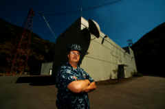
The transmitter building, a functional concrete building without windows and several stories
in height, was then constructed. Its foundation extends 35 feet below the surface, and it is stabilized
against earthquakes. The building is copper sheath-lined throughout to shield it against the intense electro-magnetic field.
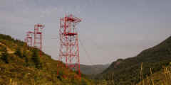
Installation of the transmitting equipment and the antenna system was completed in the summer of 1953. The giant antenna network, in effect, forms a "roof" over Jim Creek Valley supported by twelve 200-foot towers located on the crests of twin mountains. Six towers were erected on 3,200-foot Wheeler Mountain and six on 3,000-foot Blue Mountain. Ten spans of antenna were strung between them across the valley to form a zigzag pattern.
The lengths of the catenary cables range from 5,640 to 8,800 feet. From the midpoint of each catenary or span, other cables lead straight down to the towers of the busing system. The 145-foot bus towers located along the mountain side tie the giant transmitter to its antenna. On the valley floor are other towers which support the down leads and counterweights which keep the down leads in tension. There are a total of 23 towers in addition to the 12 main antenna towers.
Two Thousand Kilowatts Required
The antenna spans are designed as standing rigging to withstand 1/2-inch radial ice in
a 65-mile-per-hour gale. To allow for the ice and wind conditions expected in the area, the spans are
permitted to sag as much as 1,063 feet at their center point.
Both the transmitter and the antenna system are divided into two independent and isolated halves, each made up of five catenaries. This arrangement makes possible the operation of one half of the transmitter and one half of the antenna in the event that the other half of the antenna should for any reason be out of service. Under normal circumstances, however, both halves of the transmitter and antenna are operated, in which case the antenna system is subjected to a potential of 200,000 volts.
Two thousand kilowatts are required to power the transmitter and other facilities. Primary source of power is the transmission line from Bonneville Dam. A separate substation within the reservation transforms the incoming high voltage to 4,160 volts, three-phase, and lower voltages for use by the transmitter and other station use. A projected Diesel-electric plant will provide emergency power.
Engineering Achievements Listed
Among the engineering achievements in the design of the transmitting equipment are the
following:
(a) A conservatively rated 1,000,000-watt output from four superpower electron tubes designed
specifically for this type of service. This represents a fourfold advance from older equipments which
use eight tubes to develop 500 kw.
(b) Microsecond fault protection developed specifically for this Navy equipment. This electronic
device relieves overload faults in the superpower amplifier tubes in the fantastically short time
of a few millionths of a second and prevents the buildup of currents that could damage the tubes.
(c) Elimination of tuning controls in all low-power stages through the penultimate amplifier. Tuning
adjustments are confined to remote pushbutton control of the antenna and power amplifier tuning.
(d) Simplification of command and control functions such as the main bus controls on the operator's
supervisory console which tell at a glance (by means of lighted lamps) which units are in use and which
are in an idle or a test state.
(e) Development of a variable frequency oscillator having a frequency stability of
0.001
percent. Advanced development based on experience with binary computer circuitry resulted in
an extremely stable frequency source which may be set to any frequency in the 14.5 to 35 kilocycle
band.
Flexible Controls Arrangement
The transmitter itself is contained within an enclosure 80 feet wide and 50 feet deep. The
transmitter is actually a dual 500-kw transmitter arranged in the shape
of the letter U. Between the wings of the U is the supervisory control console including the operator's desk. On each side are
the main rectifiers followed by the exciters and 500-kw. power amplifiers.
For full power operation both power amplifiers are driven by either exciter. Either
frequency generator-monitor may be used to furnish keyed signals to the
exciter in use. The main rectifiers have sufficient capacity for either unit to supply plate power to
both power amplifiers. The idle units are thus in a reserve status and available for maintenance and
tuning. When desired, either power amplifier of the transmitter may be operated with either exciter to
provide an output of 500 kw. The idle amplifier can then be simultaneously
operated with its test load up to 500 kw.
The central supervisory console contains the extension controls and instruments for tuning the
amplifier and antenna circuits. Both frequency generator-monitor units are grouped with the
supervisory console to provide a central operating position from which the more important instruments may
observed. This assembly also includes the CW (continuous wave) and FSK (frequency shift-keying)
teleprinter tone-keying equipment. The master control panel contains meters for the switch gear, water
temperature and flow, pressure pumps, and other auxiliary equipment.
All side units of the transmitter are enclosed by a continuous steel unit in two-tone cobalt blue enamel. Each rectifier, exciter, and power amplifier is compartmentalized for RF shielding by aluminum panels attached to structural aluminum running behind the front enclosure. An elaborate safety system for operating personnel is provided. Aluminum interconnection wiring ducts and catwalks are mounted on top of the shielding structure just behind the upper section of the front enclosure.
The transmitter is situated on the second floor of the transmitter building. Power transformers, switchgear, pumps, distilled-water tanks, heat exchangers, shops, and telephone-cable terminals are located directly below on the ground floor. At the rear of the transmitter and machinery spaces are two integral helix houses, each 75 feet square and 60 feet high, housing the loading inductances and variometers used to tune the antenna circuits.
The megawatt transmitter has been designed around a special 500-kw. high-vacuum triode. Each of the two power amplifiers employs two in the push-pull circuit with the third available as a spare. The tubes are cylindrical with disk electrode connections. They are about 10 inches in diameter and 38 3/4 inches in length and weigh 135 pounds.
Amplifiers Deliver One Megawatt
The anode, grid supports, and cathode beam former are water cooled. The six-volt filament structure of thoriated tungsten will
require approximately 13 kw. heating power. Each tube requires about 500 watts grid drive for 285 kw
output at 80 percent plate efficiency. Plate voltage is 11.5 kv. The four operating tubes in both
power amplifiers will deliver 1,000 kilowatts to the antenna system.
The transmitter begins with a crystal variable oscillator which is monitored and automatically
controlled by crystal-controlled circuits. It is capable of either on-
off keying or frequency-shift keying. The oscillator output is approximately one watt. By coaxial
cable either of two such oscillators may excite either of the exciters that follow. Only one oscillator is in use at a given time.
The power amplifiers are push-pull circuits, with mica tank capacitors, Litzendraht-cable variometer tank inductances, and inductive antenna couplers. Normally the left power amplifier will drive the left half of the antenna and the right side similarly will drive the right. Provision is made, however, so that either power amplifier may be connected to either half of the antenna or to its own water-cooled dummy load for test purposes.
The intense electromagnetic field around the transmitter necessitates an elaborate grounding
system for the entire structure, including a ground screen around the building. More than 200 miles
of copper wires, cables, and screens are buried in an intricate pattern across the valley floor to provide
efficient grounding.
| 1995 Facility report - BRAC | Equipment |
Antennas |
- Primary and Secondary Transmitter Keying Circuits from NAVCOMMSTA
Stockton via leased telephone lines and/or UHF microwave circuit. - computerized Orderwire circuit between NAVRADSTA(T) Jim Creek and NAVCOMTELSTA Puget Sound and the NAVCOMM Det Whidbey Island. - UHF Microwave Link between NAVCOMM Det Whidbey Island and NAVRADSTA(T) Jim Creek. - UHF Voice Orderwire between NAVCOMM Det Whidbey Island and NAVRADSTA(T) Jim Creek. |
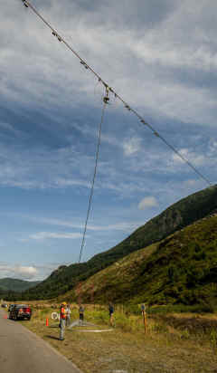
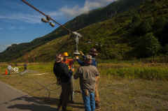
US Navy Photos - Antenna replacement work August 2012
See article here |
Antenna system model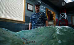 |
||
 |
 |
 |
Mobile winch ("goat")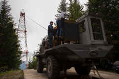 |
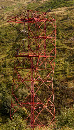
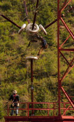
| Contractors work on the insulator of one of the 35 antenna towers located at Jim Creek Naval Radio Station. The antenna towers are 200ft tall and are atop the moutaninsides where the top elevation is near 3,000ft. | |||
 |
 |
 |
 |
 |
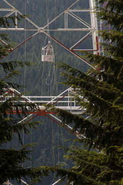
Antenna and cable inspection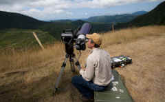 |
 |
 |